The ranging between one UWB anchor and tag may jump seriously in certain specific situations , such as specific locations in tunnels or near the high-voltage line transformer. This problem has become increasingly serious recently.
On open ground ranging range is 1-240m, and the distance can reach 300m in the tunnel under construction. But the distance can jump seriously in certain parts of the tunnel or within a certain distance from the anchor. For example, when the tag is in 80-100m away from the anchor, but the measured distance will be between 10-350m or even greater.
The PCB boards of anchor and tags are designed based on the DW1000 chip. The anchor and tags use DS-TWR point-to-point TOF ranging, once per second; both the antenna delay are 16456, the tx power is the 25 dB(the 0x1E register is set to 0x14141414, when smart transmit power contorl is disable) . The UWB channel parameters are as follows:
Integrated PA and LAN have been added to the sending and receiving circuits of anchor and tags. We had try to use filtering algorithms, however its effect is not significant, it only smoothes the data,but jumps is still serious.
Who knows under what circumstances can cause the ranging distance jump seriously ? Is there any methods that can eliminate or reduce the jump range?
You get 200m range with those settings? Are you using a satellite dish for an antenna or something?
Are the ranges always longer than truth or do you sometimes get ranges significantly shorter than truth? The two often have very different causes.
Do you have any way of viewing the CIR data from your system? A plot of the CIR data and reading the detected detection point location in the CIR is handy in this situation.
Under ideal circumstances (an open field) the CIR plot will show virtually nothing until a time value of around 730-750 and then a single large spike for the signal followed by nothing. The detection point should be just as this spike rises above the noise level.
In reality, especially indoors, the large initial spike will be followed by lots of other signal spikes, the reflections arriving after the direct signal.
Ranges longer than truth are normally where the line of sight path is attenuated too much, either due to obstructions, fading due to ground reflections or just too much distance. In this situation the direct signal is visible in the CIR data but isn’t strong enough to cross the detection threshold. There is then a reflected signal that is significantly stronger and is incorrectly detected as the direct path. Reflections can at times be far stronger than the direct signal. In the CIR you’ll see a small spike at the expected point and then a larger one later. The detected point will normally be later than the normal ~740 location.
Rangers shorter than truth are rarer but can happen, generally in very large buildings. I’ve seen it twice, in a massive aircraft hanger and in a very long straight tunnel. What happens is the UWB signal consists of a series of pulses. If a reflection path is long enough and strong enough then a reflection of the first pulse can arrive just as the system starts looking for the first pulse. This results in a spike in the CIR data before the true signal arrives, this is then incorrectly detected as the direct path and results in a shorter than truth range.
Both of these can be detected and corrected by looking at the CIR data but that is slow. A quicker solution is to look only at the detected first path location and reject the data if it looks bad. This is less reliable and throws data out rather than correcting it but it is quick and simple.
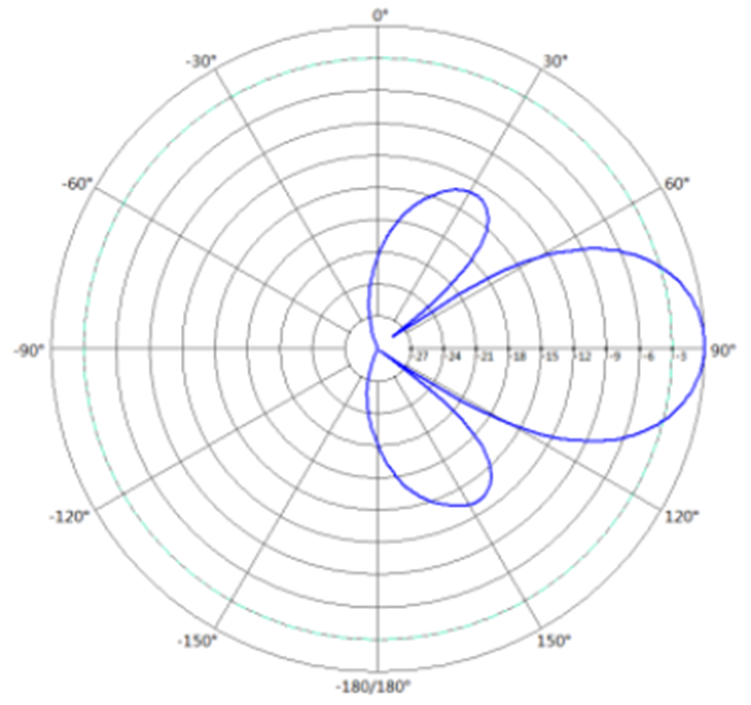
We are not using a satellite dish for an antenna, but a single polarized directional flat antenna with a gain of 14 dBi. The main parameters are as follows:
Working frequency range: 3700-4200 MHz
Polarization method: vertical
Impedance: 50 Ω
Return loss:≤ -17
Horizontal beam width:
The range is not always longer than the truth, sometimes is longer and sometimes is shorter, but the deviation is very large. For example, if the truth is 80 m, it may be measured as 200 m or 20 m. I feel that this issue is a bit complex and tricky.
Is the CIR you mentioned the register ACC_ MEM that id is 0x25 and length is 4096 ? Do we need the CIR data from the anchor or card, or both? Do we read the all CIR data every time when ranging is done?
If we want to detect and correct it by looking at the CIR data, can you provide specific methods?
The quicker solution you mentioned, i feel it will result in direct ranging failure because the data has been rejected, and the MCU may take more time.
I’ve seen range jumps of 50+ meters due to this sort of effect so what you are getting isn’t unreasonable.
Your antennna is highly directional, any chance that some of the jumps as caused by the direct signal falling into a null while a reflection path isn’t and so you pick up the reflection?
Yes, you need to read the ACC_MEM, it contains pairs of I and Q values (around 1200). Calculate the magnitude of them ( sqrt(II+QQ) ) and then plot that.
It is normally reasonably symmetrical between the tag and the anchor, they will be close enough that if there is an issue it will show up in both.
I only use this as a debug tool when manually requested rather than for normal operation. Reading that much data over the SPI link takes a while, I’d rather throw the data out and use the time to make another range attempt rather than try to recover the range from potentially bad data.
There are some quirks on reading those registers, code to do it has been posted on this forum multiple times in the past if you hit issues.
As for how to correct the data, there are probably dozens of PhDs written on how best to do that. Personally I went with the throw the data out method. But then I’m using lots of anchors and a high update rate so dropping one or two anchors as they move through a bad zone isn’t a big issue.
Yes, we use the highly directionnal antenna for long distance.
Recently, we had done some tests, such as setting the anchor TX power to 0.5dB 、 prf to DWT_PRF_64M and premibleCode to 9, and the tag is the same as anchor, but the problem still exists.
In most cases, the measured distance is smaller than the truth today. The measured distance is still over 220 m when tx power of anchor is 0.5dB.
I have one questions now , if i use channel 2 with a center frequency of 3.9936GHz, how can i set the register value if I want to fine tune this frequency.
Hi, I am facing the same problem as well, i use 4 anchors and one tag, it will show many large outliers, and in 1 minute it will jump to 100 meters and drop slowly, and jump to a high value again in a very short time, did you have the solution?