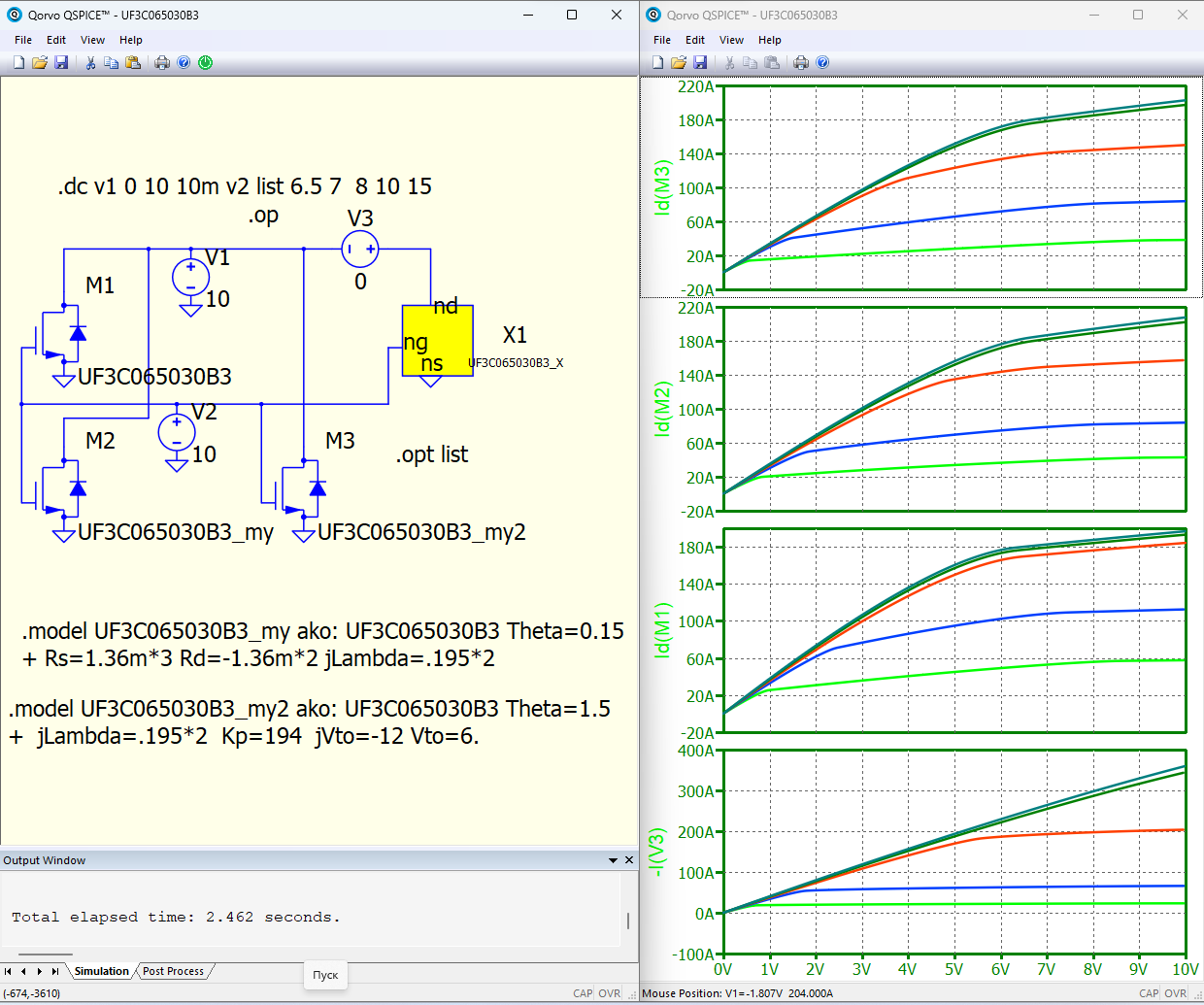
Which models SiC FET UF3C065030B3 are correct - in the QSPICE program or on the Qorvo website (UF3C065030B3 - Qorvo)?
UF3C065030B3.qsch (8.5 KB)
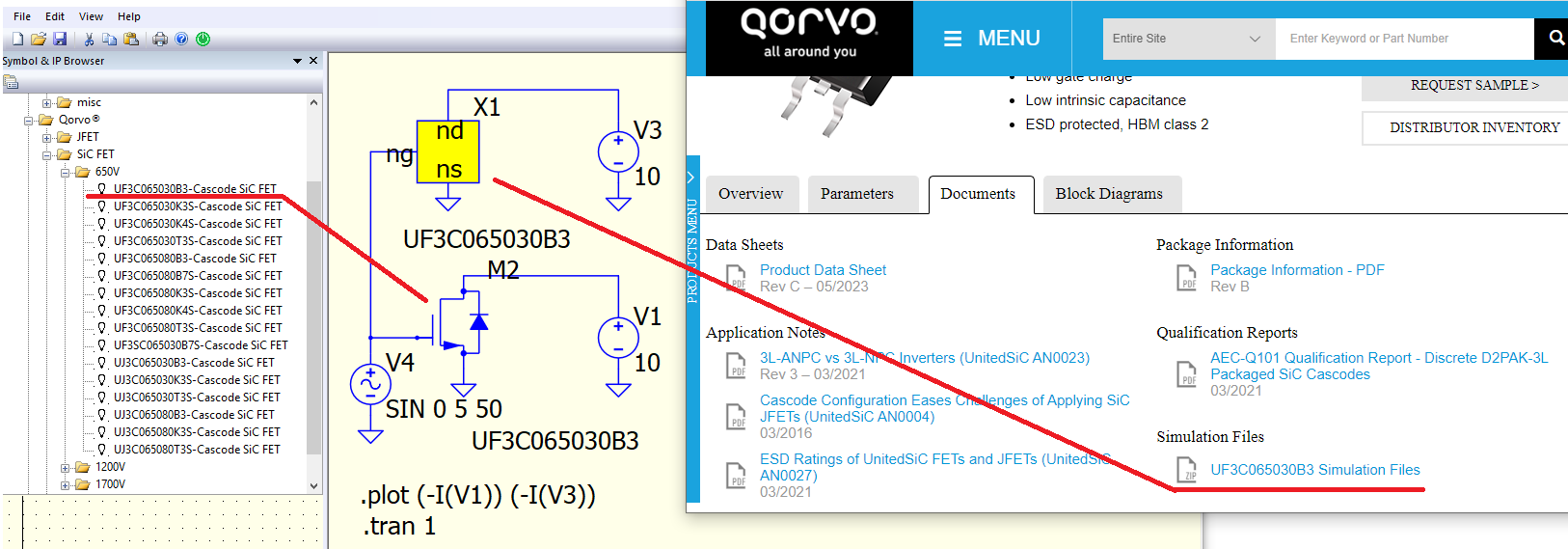
And LTspice (from Qorvo website)
Which models SiC FET UF3C065030B3 are correct - in the QSPICE program or on the Qorvo website (UF3C065030B3 - Qorvo)?
And LTspice (from Qorvo website)
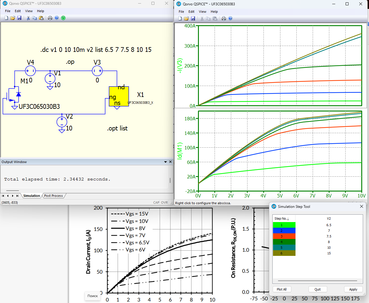
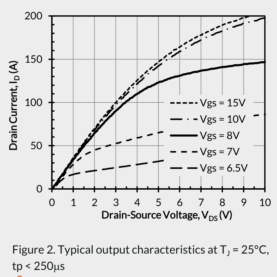
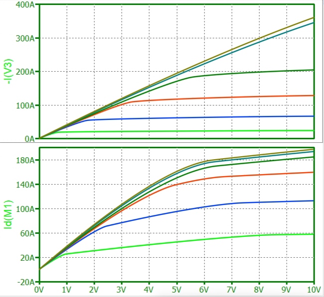
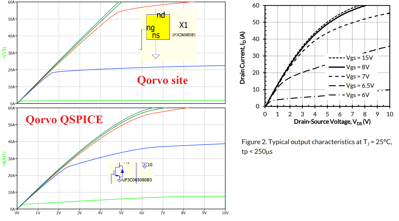
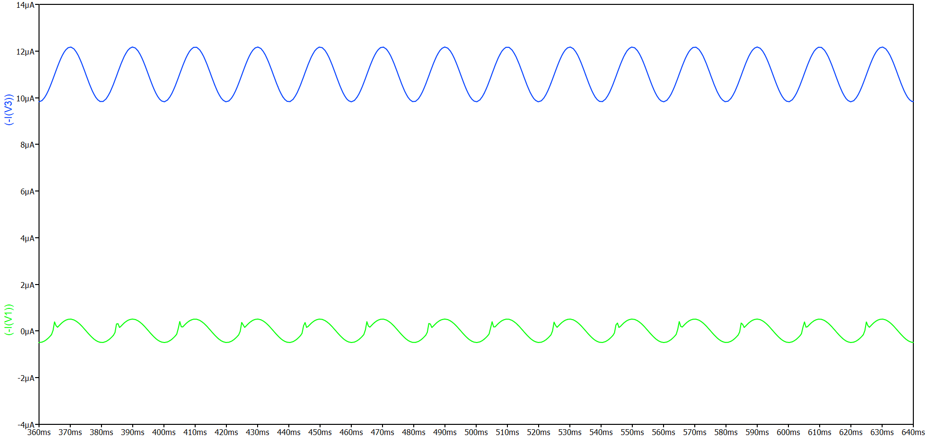
Not one. I showed the volt-ampere characteristics of the two models and the datasheet. In addition, I found a BUG - wrong current direction in the voltage sources.
Tell my surprise at the bad model to the model developers.
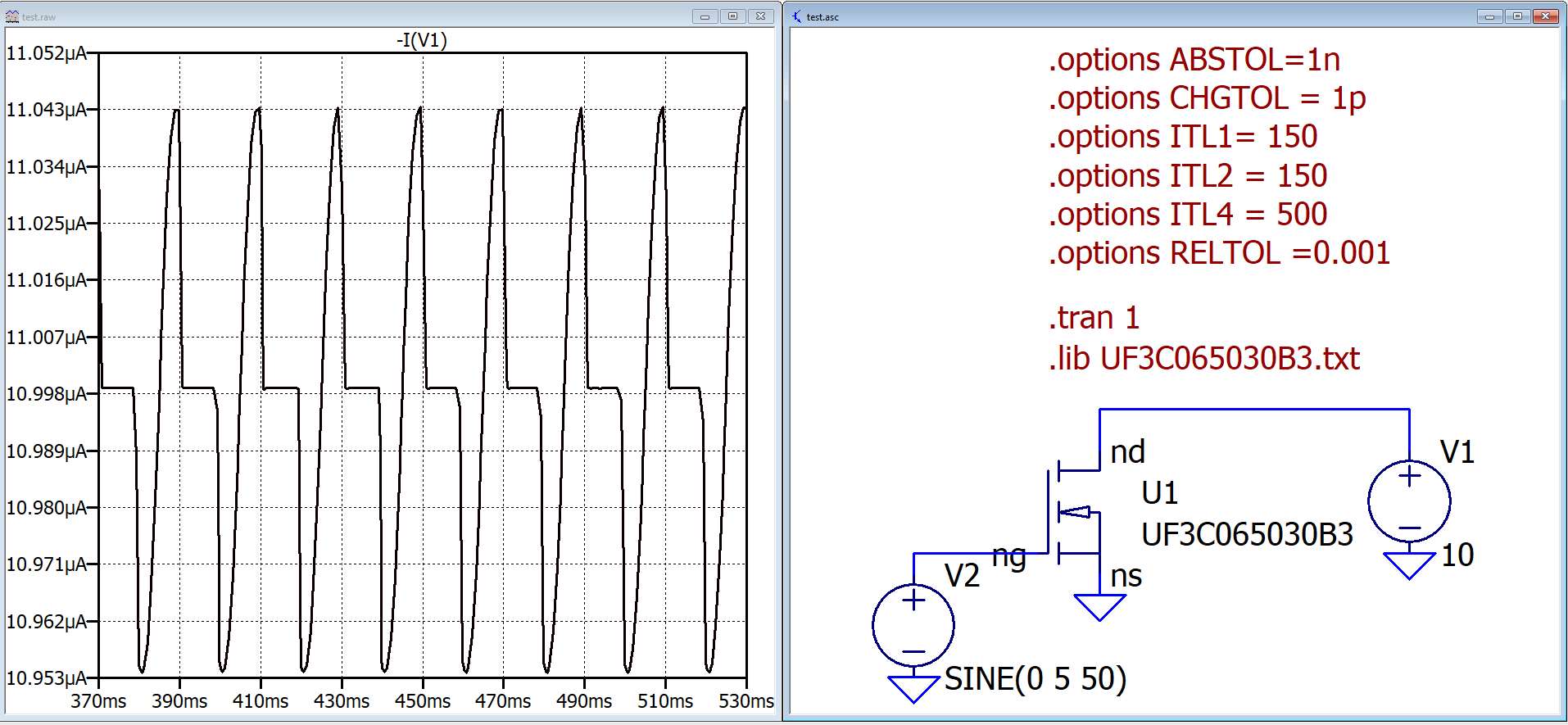
I don’t think there’s an error in the current direction of the voltages sources. The industry standard there is current direction is from plus to minus through the source. Every SPICE program works that way and it has to be compatible with models that call such Thévenin sources in behavioral sources. I don’t like the convention, either, but it is what it is. That’s why when you click on voltage source it plot “-I(V1)” instead of “I(V1)”.
I can’t see what models you’re using, so you can either e-mail them to me for my opinion on them or you can look at the datasheet output characteristics and see which you feel agrees better.
–Mike
I realized my mistake and corrected my message - I threw out the reasoning about the direction of current. I had some kind of obsession. And about the model: I will try to correct it, I have a lot of experience in fitting models to datasheets.
Really I see now that I didn’t fully correct the post. I apologize.
I attached the SiC FET UF3C065030B3 (Qorvo) model in the message. The question is, why provide models of incorrectly working devices on the website and in the program? They do not meet the technical specification and they are different.
Thanks for the solution, but other Qorvo models have the same problems. I took the following transistor UF3C065080B3 - the data does not match. Why include incorrectly working models on the website and program?
Recommendations for correcting the model: