I am just wondering if anyone aware that when I use uic in .tran directive somehow the waveform data does not stretch down to 0s. Instead it will start at the very next timestep.
While if I remove the uic, the waveform will start from 0s.
Honestly, it doesnt bother me at all (as I havent been made aware of it for a long time). Nevertheless, its still a curious thingy.
This same phenomenom seems to be happening when you do transient simulation and parameter TSTART is larger than zero, so saving data is delayed. When TSTART is zero, then first datapoint is saved at time 0 s.
Taking FFT using rectangular windowing will have worse noise floor when compared situations TSTART zero and not zero and data lenght is same. This may be due to missing first sample at time TSART and data is not continuos over simulation period.
I typically start saving data with when transient effects have settled, but it would be nice to have that same good noise floor with FFT as without using TSART parameter with TRAN command.
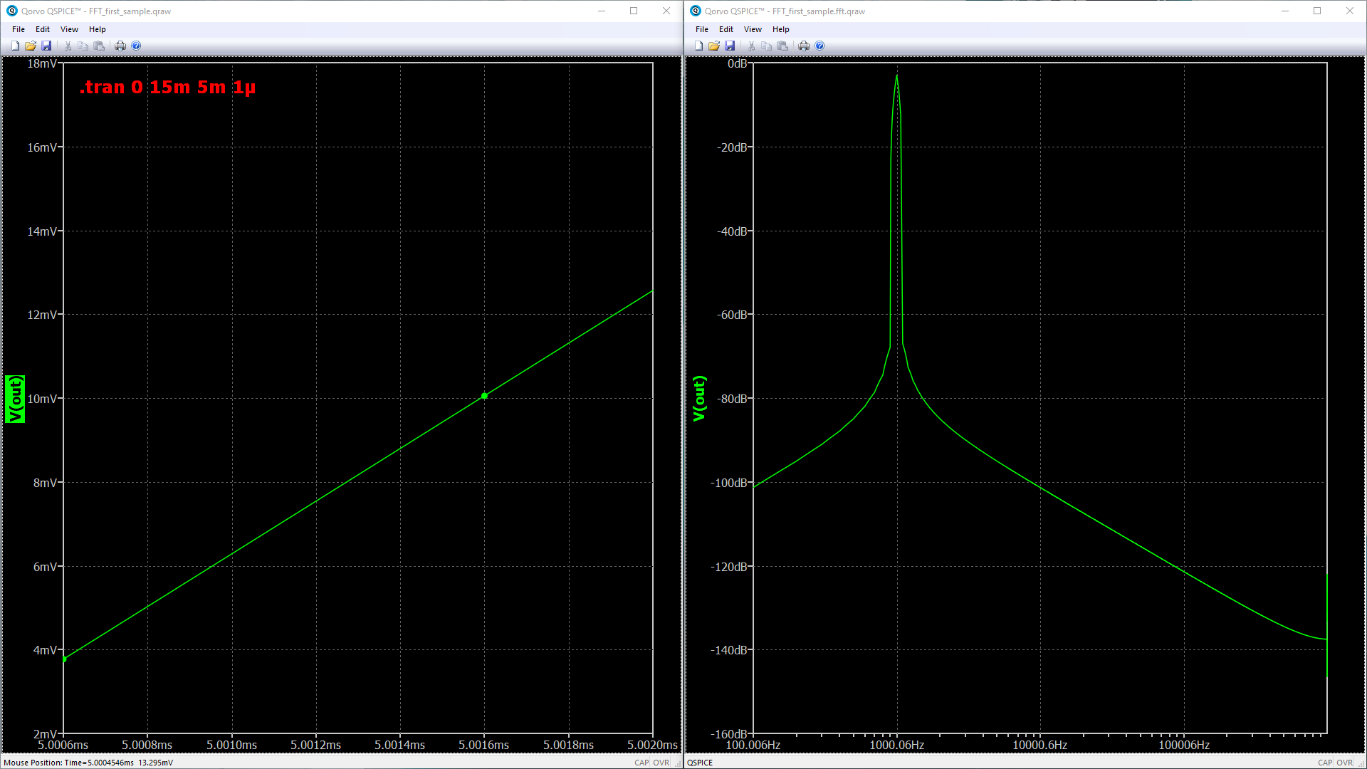
Unfortunately I could not attach any files and embedded figures are limited to one. But if you simulate following netlist with “.tran 0 15m 5m 1µ” or “.tran 0 10m 0 1µ” and take FFT, you can see different noise floor.
V1 out 0 sine 0 1 1K
.tran 0 10m 0 1µ
.plot V(out)
.end
I dont know the possible root cause of your issue.I have checked your FFT example and yes the difference is massive.
However, you may notice in the time domain result, that right after simulation start and right before simulation end, there are multiple timesteps crowding compared to the rest of the simulation.
Another issue that should bring up to your attention is the number of data points are decimal based. However, FFT original algorithm require the input time domain data to be binary based (2,4,8,16,… ). To my knowledge when the input data is not exactly matched to binary based, then it is common for people to use zero padding to fill the rest of the data.
For example if you enter 10k data points, the closest binary value is 16384. So, what will happen is you will have this time domain data to be fed into FFT algorithm: [3192 of zeros , actual data, 3192 of zeros]
*unless if Mike uses different FFT algorithm.
When you feed a pure sinewave into FFT, the result should be 1 point of a very sharp spike. However, as you can see about this on your own the fundamental signal seems to have very wide shoulder. Which I think is indicative of spectral leakage.
I hope we can highlight this issue to the lead developer and the major contributor in this forum @Engelhardt@KSKelvin
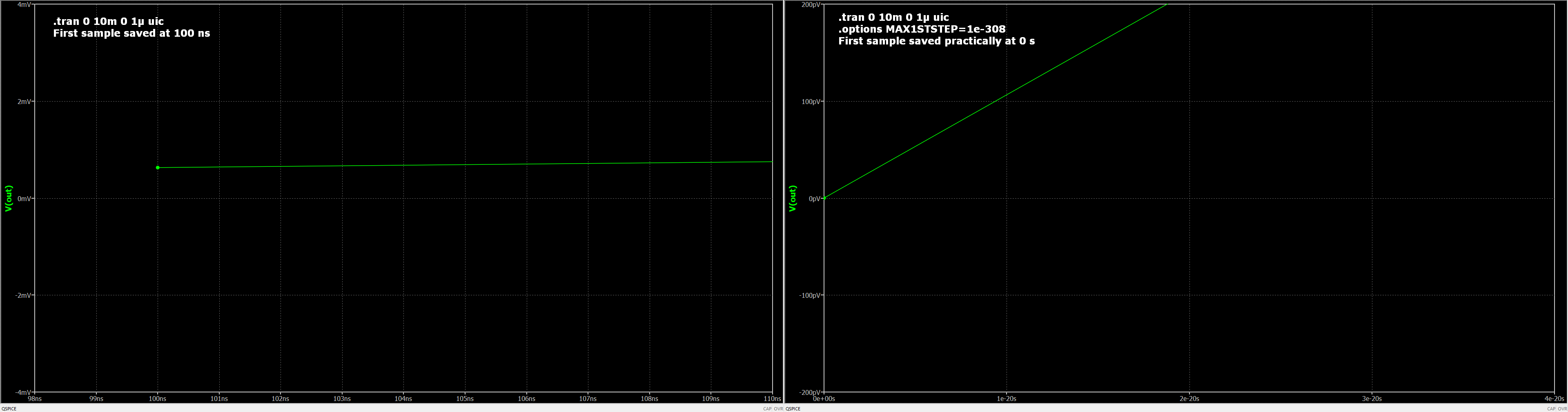
Latest few versions of QSPICE got updates to these both cases shown in above posts.
03/02/2024 Implemented a new option, Max1stStep, to restrict the size of the first timestep of a .tran without restricting latter timestep sizes.
Now you can force first sample close to 0 s. Zero is not a valid value, but very small values are accepted. I tested this with “.options MAX1STSTEP = 1e-308” and the first saved waveform step is practically at 0 s.
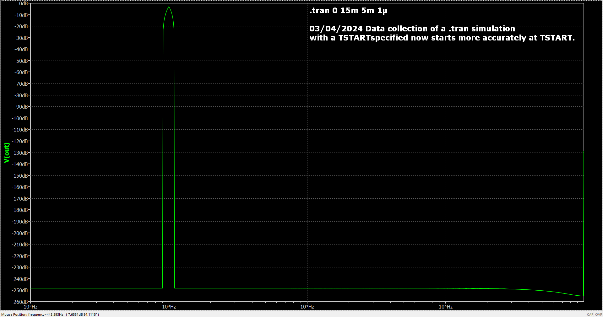
Simulator was also updated to take sample more close to TSART timepoint. As suspected, this made FFT look much better due to lower spectral leakage, see figure below. It is now easier to use rectangular windowing with FFT. Obviously, it has been possible to save longer period data and use FFT start and stop to achieve rectangular windowing. But this was nice, quality of life update. Thanks Mike.
03/04/2024 Data collection of a .tran simulation with a TSTART specified now starts more accurately at TSTART.