In SPICE simulation, to perform AC (.ac) or Transient (.tran) analysis, it first runs a Bias Point analysis (.op) beforehand. This process is similar to the circuit analysis you learned in your undergraduate course.
In AC analysis, calculations are based on small signals, linearizing the circuit around its bias point. Therefore, the first thing you should do is verify that all DC voltages are correct. In real-life scenarios, you typically apply DC voltage to ensure everything is steady before applying an AC signal. It’s important to understand that this also applies to transient analysis. At time 0s, by default, it starts with the bias point solution unless you use the UIC in the .tran directive or assign certain node voltages or device currents with the .ic directive.
In summary, the .op analysis is something you should be aware of before running AC or transient analyses, unless you fully understand your circuit and know what the DC solution should be according to your expectations.
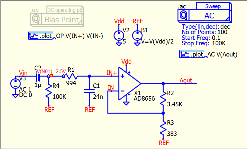
In Edit > Preferences, there is an option “Enable operation point display” that keeps the .op analysis result file. You can monitor your bias voltage (DC solution) by hovering your mouse cursor over a voltage node.