I wonder if it is possible to simulate wave resonance in a coil?
What do you mean with wave resonance in a coil? Something like LC tank circuit or something else.
Best regards
Hello,
I mean an oscillatory process when the length of the coil wire is equal to 1/4 or 1/2, etc., of the oscillatory wavelength.
Hello Ivan,
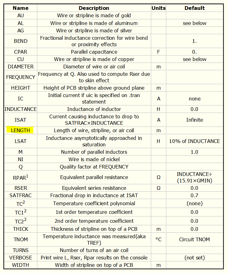
Thanks for the table. What to do with it?
Pease, tell me if QSpice is able to simulate wave resonance process?
@xel ,
Determining a wave resonance (Fres) in a real coil “on paper” can be very tricky.
The magnetic field generated has a 3D characteristic. Therefore ANY magnetically influential materteral nearby will alter the Fres of the inductor.
The closest you can get to a simple Fres is if the wire is NOT in a coil and resides in free-space with no ferric material nearby. The wire is straight and has a length. This is where the length parameter can be used alone.
As soon as you coil the wire, the magnetic field generated will effect other parts of the coil to change the Fres. It will also have a Isat factor.
If you coil the wire around ferrite (or even non-ferric) material, it will also have a influence on Fres.
I’ve worked in the both the motor drive and RF disciplines. It is almost a Herculean challenge to provide a good calculation of a coil’s parameters on paper.
The usual way this is done is a two-step process:
- Use an LRC meter to measure the coils parameters which should include, Fres, Rs, and other potentially important parameters. This will give you a very good starting point to begin your design.
- Using the info from 1), place the coil in a real circuit. Then use a network analyzer (or spectrum analyzer), to determine the actual Fres for your design.
If these steps seem to be too cumbersome, I can understand.
In a motor design, you might be able to use just step 1). Motor drive efficiency may not be to critical. Additionally, EM emissions can be tuned with a decent cap to change the resonance found in EMI testing.
However, in an RF design, you usually need all the steps since RF Tx and Rx efficiencies will be critical for the best possible range. RF emissions will be important for meeting country-by-country homologation regulations for bandwidth and harmonics.
Len
Hello LEN,
Thank you very much for your informative answer. I feel like you are not new to this topic.
As for creating a coil model for Spice, it is indeed quite a difficult task.
But the electronic domain does not require good precision. This means that distortion of 5%, 10% and even 20% will do.
Therefore, the calculation can be performed with assumptions and limitations. All this will make the task easier and will make it executable.
I have a very interesting article, but I can’t upload it as a new user. If you are interested and send me your email address, I can send it directly.
Best regards,
Alex
@xel ,
As I indicated in my previous post, accuracy in the coil parameter is very critical for an RF design. Less so for a motor driver design.
It appears you don’t need a coil in a critical design.
A good starting point is to assume a optimal coil and capacitance for your tank circuit. Therefore you can use the LC equation to determine the ‘L’ part of the equation using a known ‘C’ which you wish to use.
When you start to develop your circuit in real-life, measuring the ‘L’ and ‘C’ parameters using a LRC meter will help you to create a reliable circuit in production if this is your ultimate aim.
Len