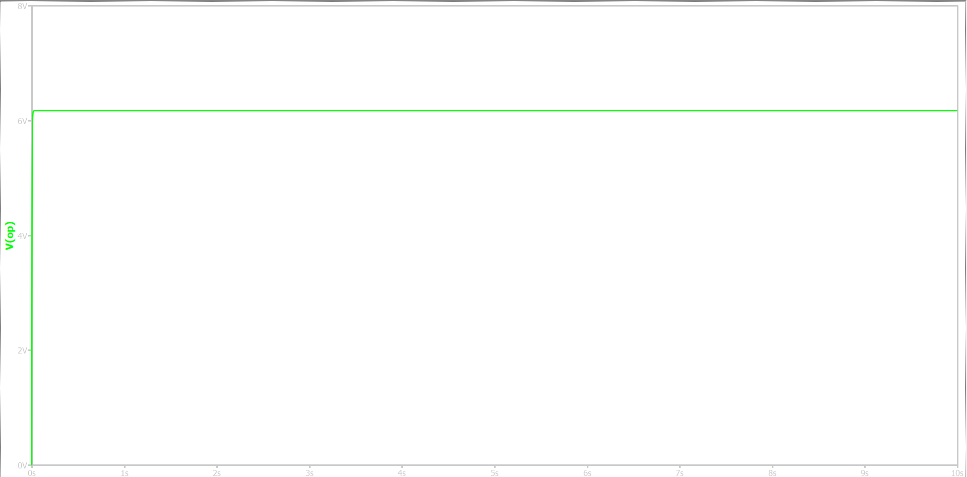
I have been working on implementing different control methods for a boost converter design and I have this issue with voltage mode control where changing the feedback resistors changed the transient response. I tried switching to 1K and 78K and set the reference voltage to 5V but this is my response:
Expecting 395V.
This also happens when I change the R and C values of the compensator. VMCtrl.qsch (16.7 KB)
This current design has a crossover frequency at 250Hz and phase margin of 60. I used matlab to calculate the R/C values. If anyone is able to explain what’s wrong with my implementation, I would greatly appreciate your help.
Hi,
With your explanation I cannot figure out what resistor are you changing from 1k to 78k, but I’m able to see:
Your resonant frequency is very close to the RHPZ of the boost and that complicates the compensation, specially for a voltage loop. Instability is guaranteed.
The Zout of the combination of Ra and Rb is to low, it should be much bigger than R1.
A classical approach for stability in terms of phase and gain margin is not suitable because of the RHPZ. Try the nyquist chart better.
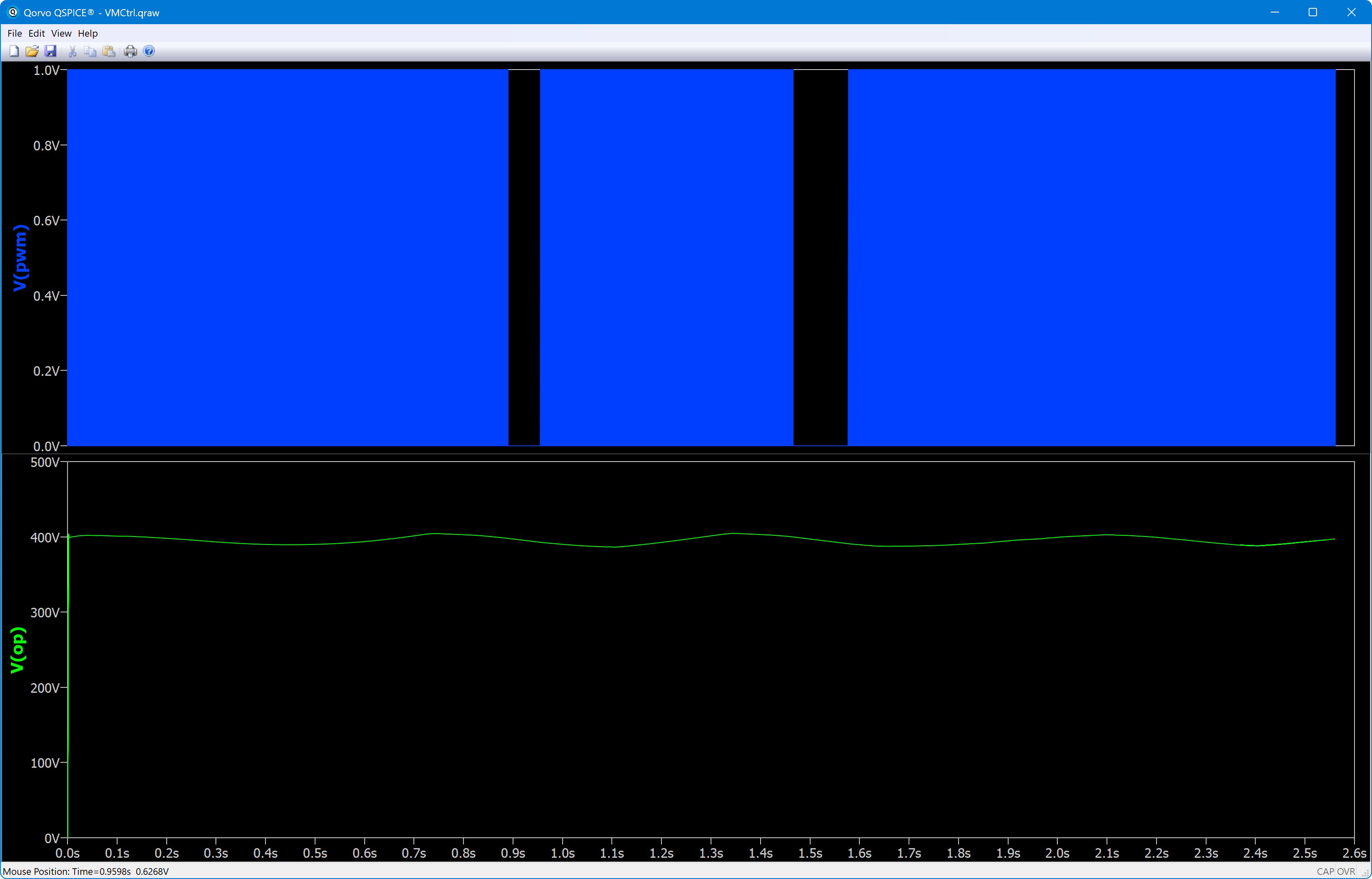
You need to change the on voltage of your ramp generator, V1, from 5 to 10 to match the output range of the error amplifier, A1. With that change the simulation runs and produces about 400 V but it is not well regulated as seems to oscillate.