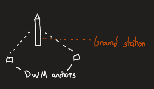
Question 1: I’m working on integrating the DWM3000 module into my avionics bay for a rocket project and was wondering, what’s the recommended vertical keep out distance? I will need to place a DC motor and maybe some other metal parts above the module vertically. The anchors will all be below (i.e. there are no anchors above the module or DC motor, only below). Below is an image showing what I mean.
Question 2: if I have carbon fiber rods mounted to hold the avionics bay together, would that cause significant interference to the RF module? Below is an image showing what I mean.
Mounted like this, antenna on the DWM3000 radiates to the sides, like a donut around the rocket. Assuming the outer shell is not metal. See radiation patterns in the DWM3000 datasheet.
The radiation pattern has a null towards the top, so 1cm between the top of the antenna and the PLA should be enough to avoid de-tuning. Carbon fibre rods are not a problem.
What kind of distance are you planning to measure?
I’d be tempted to put the module/pcb the other way up, as you have it shown your PCB will be partly blocking the modules antennas view of the ground. Of course this then puts the antenna closer to whatever is below it (presumably a motor) which may also block the view even if its distance/material doesn’t cause other issues.
The carbon rods may may a slight difference to the measured range when they are directly in the path of the signal but otherwise should be ok. So you may get a slight orientation dependent error but unless you want to push for the absolute best possible accuracy probably not enough to matter.
As Matthias indicated the antenna pattern is more to the sides rather than vertical, most positioning systems are dealing with things that are roughly all at the same height, so your range may be less vertically than horizontally. Unfortunately there is no simple solution to this, if you rotate the module you start getting significantly different gain in different directions and possible polarization miss-matches. The complex solution is to use a completely different antenna but that’s not something you want to get in to.
How large would that orientation dependent error likely be? I am going for accuracy, but if it’s only going to be 1-3cm difference then it’s not a huge deal for me. The main issue with mounting the module the other way up is I’m planning of having a 915 mHz antenna mounted to the bottom, which will likely be longer and force me to move the avionics bay further down. Or I might be able to mount that to the outside of the rocket, but I’m unsure atm if that’s a possibility.
So you’re saying that the radiation pattern of the antenna is mostly to the sides and not much vertically? Is that going to make it very difficult to get a signal to the rocket? Are there ways to mitigate this problem based on orientation of the anchors?
I doubt you’ll see more than a few cm of additional orientation dependency. Even with nothing else around the module orientation already has an impact on measured range.
If you look at the datasheet (https://www.qorvo.com/products/d/da008334) pages 16/17 it shows the antenna gain patterns.
From the second diagram on page 17 you can see that the gain is roughly constant from around 15 degrees to 135-140 degrees. So if you point the antenna up the signal is poor directly above it but picks up once you get 15 degrees off vertical. It remains about the same until about 45 degrees below horizontal and then starts to vary significantly.
Having said that these patterns will be changed by the environment, the shape of the carrier board and the parts around it will have a significant impact. Only view the patterns in the datasheet as rough guides.
I see what you mean now on why switching PCB orientation might be beneficial. If I have 3 base stations around 15-20ft from the launch pad in a circle, I think that’ll likely fix things though. If not I could always just flip the orientation.
How hard would it be to use a different antenna? I’d assume I’d have to integrate the DW3000 myself then?
Using a different antenna is tricky. Generally yes, you are looking at a custom board design using the DW3000 chip directly. Which is not something you want to get into if you can avoid it.
On one of my early DWM1000 based prototypes we removed the fitted antenna and soldered a short RF cable to an SMA connector on to the pads the antenna was using. It worked and allowed us to use a better antenna that was well away from the electronics and so get a better pattern. But from both an RF signal quality perspective and mechanical reliability it was not a good solution. When it did work we had to re-do the antenna delay calibration every time we used it. It worked well enough to prove the system design before making a custom board but wasn’t something I’d recommend.
In may ways the antenna choice is a bit like the firmware/application side of UWB. If you can make one of the off the shelf solutions work for you then use them. You can always make something better suited for your application by doing it yourself but it’s a lot of work, you need to weight up whether the benefit is worth the effort.
Ah, I see. Yeah I’ll check out the module and see if that works first in that case. One other question: I also have a 900-915 mHz antenna mounted in the same assembly, and the current way I have it the path for the UWB and the 900 mHz have some crossover (UWB is at top, 900 mHz is at the bottom). Do you think I should flip orientation or move the 900 mHz further up inside the rocket in order to mitigate this? Or is it not something significant to worry about?
They are different enough in frequency I wouldn’t worry about it.
What would be more of a concern to me is if you are using standard 900MHz antennas and are orienting them vertically then they have a null directly above / below them, if the base station is almost directly below the rocket then the signal strength will be very poor. You may have enough power that this isn’t an issue but it’s something to keep in mind.