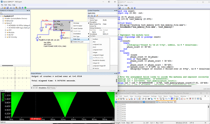
Thank you for all your efforts on this simulator, it is a valuable contribution to our discipline! I am attempting to build up components for a communication circuit. I started by generating an NCO in verilog. The output of my NCO is declared as a shortfloat(32bit) data type. I would like this signal to be able to drive analog circuits in the future. I am unable to generate negative numbers or any exponential numbers. Perhaps the waveform viewer is not interpreting the number correctly? I have assigned numbers consistence with “IEEE 32bit floating point” as well as many other bit assignments in an attempt to generate any negative number in the waveform viewer without success.
I’m new here so I’m not sure if I’m allowed to respond ![]() However I was playing with something similar. I created simple DDS (NCO) using Verilog that outputs to a simple DAC implemented in C++.
However I was playing with something similar. I created simple DDS (NCO) using Verilog that outputs to a simple DAC implemented in C++.
Verilog code:
module dds_simulator_x1 (
input [15:0] step, // Changed input type to match the phase_accumulator type
input clk, // Single-bit clock signal
output reg [15:0] out // Output should be a reg if driven in always block
);
reg [15:0] phase_accumulator;
reg [15:0] sine_lut [0:255];
integer i;

initial begin
    phase_accumulator = 0;
    for (i = 0; i < 256; i = i + 1) begin
        sine_lut[i] = 32767 * $sin(2 * 3.141592653589793 * i / 256);
    end
end

always @(posedge clk) begin
    phase_accumulator = phase_accumulator + step;
    out = sine_lut[phase_accumulator[15:8]];
end
endmodule
C++ DAC code:
// Automatically generated C++ file on Thu Aug 1 14:11:20 2024
//
// To build with Digital Mars C++ Compiler:
//
// dmc -mn -WD dac1_x1.cpp kernel32.lib
#include
#include
union uData
{
bool b;
char c;
unsigned char uc;
short s;
unsigned short us;
int i;
unsigned int ui;
float f;
double d;
long long int i64;
unsigned long long int ui64;
char *str;
unsigned char *bytes;
};
// int DllMain() must exist and return 1 for a process to load the .DLL
// See DllMain entry point (Process.h) - Win32 apps | Microsoft Learn for more information.
int __stdcall DllMain(void *module, unsigned int reason, void *reserved) { return 1; }
// #undef pin names lest they collide with names in any header file(s) you might include.
#undef DDSin
#undef Vout
extern “C” __declspec(dllexport) void dac1_x1(void **opaque, double t, union uData *data)
{
short DDSin = data[0].s; // input
double &Vout = data[1].d; // output
// Implement module evaluation code here:
double max_volts = 5.0;
double lsb = double(max_volts/65535);
double lsb_noise = lsb/2.0;
double random_factor = 2.0* ((double)random(23234)/RAND_MAX) - 1.0;
double random_noise = 4.0*(2.0* ((double)random(4354)/RAND_MAX) - 1.0);
Vout = double(DDSin)lsb + random_factorlsb_noise + (lsb*random_noise);
}
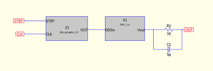
I put it inside of a hierarchical model. The internal schematic is below:
this image shows the implementing top level schematic
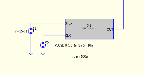
not sure if the images will be displayed properly. I do get negative values out. However I noticed that my output is loaded down by a butterworth LP filter. Not sure why that is happening.
Hope something there helps,
Ed
Hi, Mike.
I’m not really a Verilog guy but would happily take a look at it. Gonna need the schematic and code though. Since you’re new, you can’t upload yet but that permission gets granted pretty quickly I think so try daily. Or post it somewhere else (Dropbox, etc.).
–robert
By default, C-Block component outputs have a 1K impedance. You can change this with the ROUT instance parameter. See the QSpice help topic for " Ø-Device."
Edit: Well, maybe that’s not it. In the past, I’ve always added a resistor to GND to solve such problems.
–robert
I’ll give that a try and take a look in the help files.
Thanks,
Ed
@epl1000 If you don’t solve it quickly, maybe upload schematic and code when you get required permission or post elsewhere with a link (e.g., Dropbox).
What you posted appears have been pasted without using “preformatted text.” (See the little gear at the top of the edit window.) Be sure to use that when posting code – otherwise embedded text gets interpreted as special codes and the actual code gets corrupted. For example, the following from above doesn’t look like valid code:
I think that it's supposed to look like this:
[quote]
Vout = double(DDSin)*lsb + random_factor*lsb_noise + (lsb*random_noise);
[/quote]
–robert
I’ll definitely do that if I can’t figure it out soon. Also, thanks for the tip on the formatted text. I was wondering what happened to the formatting.
Ed
NCO.qsch (4.2 KB)
nco_x1.cpp (854 Bytes)
nco_x1.v (1.6 KB)
Here is the simulation of the NCO. Attached, Note the “always block” at the end of the NCO_x1.v file has various assignments (a few examples). I tried to shift the bit assignments though most of the range to see if I could get a negative number or negative exponent without success but I left the code making the msb high. Depending on the bit mapping this may not be appropriate of course but indicates my thinking on this number format explorationProcessing: NCO.qsch…Processing: nco_x1.cpp…
nco_x1.v (1.6 KB)
.
And the memory file… you will need to change the extension to .mem
hex_memory_file.mem.txt (1.5 KB)
OK, Mike, like I said, I’m not a Verilog guy so maybe I won’t be any help at all…
Looks to me like there are mismatches in data types:
- In the *.v source, you have
output reg [0:32] out;That’s a 33-bit register and won’t map to a C integer type. - In the schematic, the Out port is set to shortfloat(32-bit). I think that it needs to be integer for 32-bit signed value.
- In the *.c file, you have
data[5].f = (*instance)->out;so the union element needs to be changed to .i or .ui (i don’t think it will matter to the code but ‘.i’ would be clearer). If I understand the work flow correctly, regenerating this file should generate the correct data type.
In case you’re not aware, the QSpice DLL interface stuff is a bit fragile. If you change the schematic ports and do nothing else, QSpice will change what it passes into the DLL, how it translates values into and out of the component. QSpice doesn’t warn of mismatches between what it’s sending and what the component is expecting. To keep the component side in sync with the schematic, you need to regenerate the *.c and *.v files, add your changes back into the code, and recompile. It’s a pain but it will save hours of frustration.
Anyway, with those changes (maybe more, I forget), I get negative values on Out:
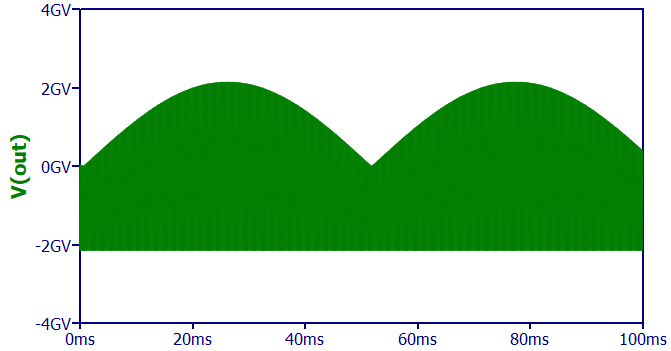
Please do let me know if that solves anything or not. Otherwise, it will keep nagging at me. ![]()
–robert
Hi, Mike.
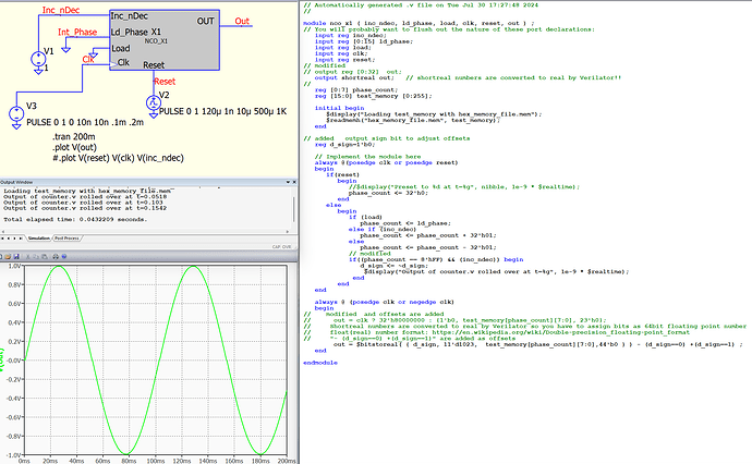
I made some modifications to your Verilog code to display sine wave results. However, I wouldn’t recommend using it because I turned it into “spaghetti code.” ![]()
According to the Verilator manual, “shortreal” numbers are converted to “real” by Verilator. Therefore, I think it’s better to use float (real) instead of shortfloat (shortreal) as a port type for Verilog coding in QSPICE.
It was a good learning experience for me. Thanks!
NCO.qsch (4.2 KB)
nco_x1.v (2.0 KB)
