I have just started to test the suitability of the dwm1001c sensors for the positioning of drones during landing. I have conducted experiments with one tag mounted on top of the drone and 4 anchors placed in a square formation 4m apart and on tripods 1m high. The idea is to land the drone within the square encompassed by the anchors. The anchors positions were set using the DRTLS app. The app was also used to set the update rate of the sensors to the max setting of 10Hz. I have also used a passive anchor which is connected to a raspberry pi kept close to one of the sides of the landing area. The position estimates are then logged through the passive anchor through serial with the raspberry pi.
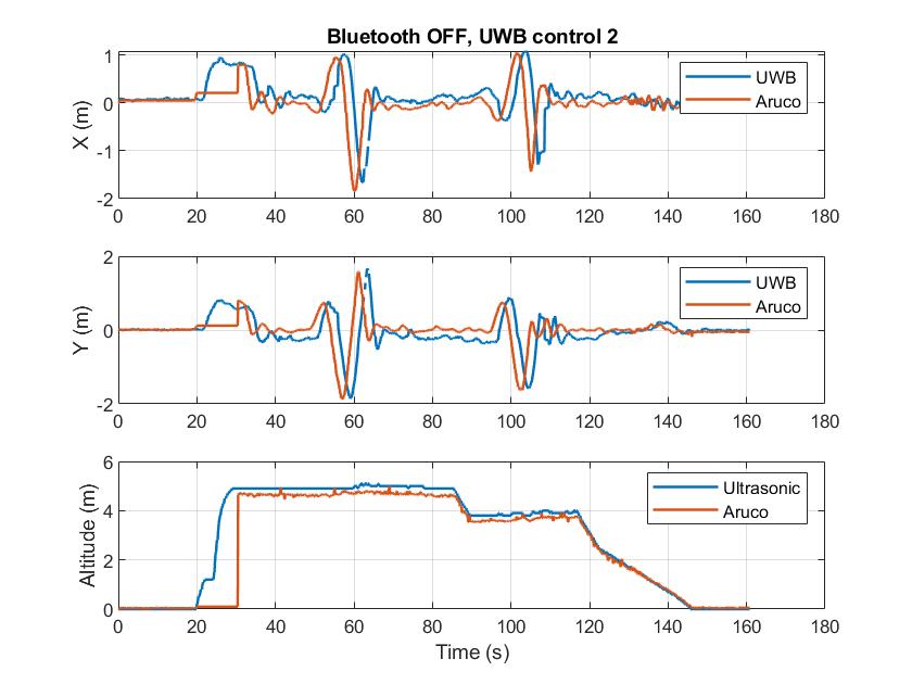
During many of my experiments I have noticed that there is considerable latency (>1s) in the positioning with the UWB sensors compared to other visual marker based systems such as the Aruco/ AprilTag method. I have attached a graph which plots the UWB positioning along with the Aruco for one of the experiments. This graph clearly shows the time lag of the UWB estimates. I suspected the reason for the latency was the due to the sensors being connected to DRTLS app via Bluetooth. However, even with the app closed and phone off, the latency in the positioning was still present. What could be the reason for this latency and is there any way I can minimise it?
The latency isn’t inherent in UWB, it is a result of the protocol and firmware used for calculating the position. So while it can be reduced getting it down to something suitable for real time control is tricky, you can’t do it using the out of the box code supplied. You would be looking at creating your own firmware for the system.
But if you were to do that then it is possible.
Warning: blatantly commercial plug
Or you could buy one off the shelf.
We have a system that will give 100Hz positions with fixed latency of 60ms.
Here is a video of using it to steer a car https://vimeo.com/363324210
And here we are using it to position a camera and then in real time use that data to move the camera in a virtual world https://www.youtube.com/watch?v=UqX9_OetZRY
It’s also worth noting that currently UWB radio regulation in most regions do not allow stationary UWB radio anchors outdoors, so this might limit usability for drones.
As Andy said, the 10Hz polling limit is set by the protocol of PANS (the demo firmware on the DWM1001), not UWB radio or the DW(M)1000. Using a custom solution a way higher polling rate can be achieved, but framing often becomes tricky.
See also this comment that might be of interest: SFDLED output pin activation delay
PANS is designed as a general purpose demo, it doesn’t try to minimize latency.
Thanks guys for your quick reply. Good to hear the latency isn’t an inherent problem with the technology.
Andy, would you happen to have kits more suited to drone applications? The ones in the video seem too big to mount on our drones.
Seppe, thanks for the info regarding the regulations. Since we’re based in the UK, the FCC regulations won’t apply to us but I will keep a look-out for similar regulations from Ofcom.
The original application was automotive so size wasn’t much of an issue.
We are working on a smaller formfactor but it’s still not going to be tiny so it’s probably only going to be suitable for larger drones.
We have tested it briefly on a drone, I don’t have the results to hand but should be able to find them if it’s of interest.
Hi Andy, some results of your system for real time control of drones would be great.
Few questions, what are the driving factors when it comes to the size of the tag? Is a smaller formfactor with suitability for real time control possible with the current tech? Thanks again for your help.
The on drone test wasn’t controlling it, we were just measuring the location. We had a 20 Hz optical system also tracking it to give us the true location so we could measure the performance. I’m trying to find out who has the log files from that test, I wasn’t there that day.
The size of the larger units is mainly driven by 3 items:
We use an antenna that is significantly larger than the ones on the standard modules, we find this gives better accuracy.
The unit includes a good quality IMU module which is fairly large. Our automotive system is designed to switch smoothly from indoor UWB to outdoor RTK GPS. But it takes a while to lock on to GPS when you drive outside so we need an IMU that won’t drift by more than a few cm during that time.
And finally the system is IP67 waterproof which makes for larger connectors and adds a little bit for the seals.
The smaller system in development consists of an antenna dome that’s around 5 cm across and 3 cm high and then a processing module that’s circular with 10 cm diameter x 2 cm height (all sizes approximate, I don’t have one in front of me right now). It has far smaller but lower spec IMU since it’s not intended to transition from indoor to outdoor.
The processing module could in theory be shrunk, currently we re-use the same PCB between systems so there are unused features and some dead space on the board. But that comes down to the commercial situation, the size is good enough for the markets we’re mainly looking at right now and so there is no justification to spend the money shrinking things.
Other than the IMU the performance should end up being much the same, the same 100 Hz output with the same latency.