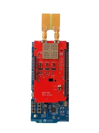
I am user of QM33120WDK1 Dual Antenna - DWM3001C as an anchor and a tag.
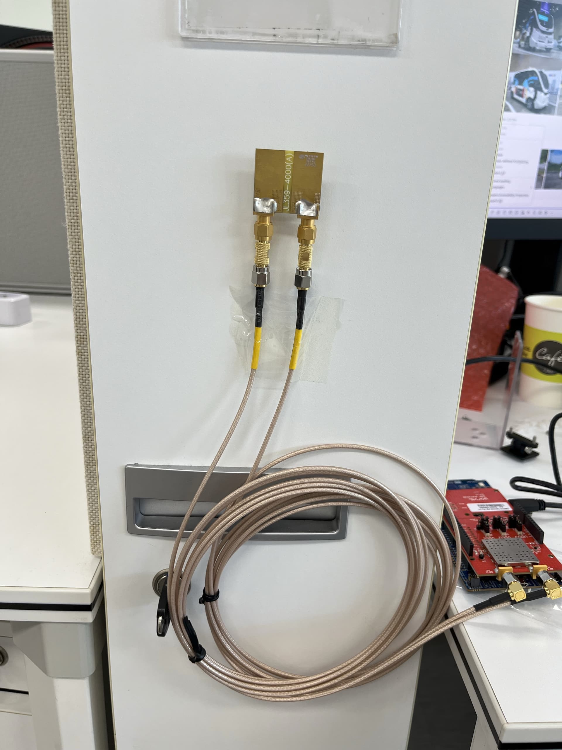
It worked properly with basic setting, but after put sma cable between the module and the antenna on Dual Antenna QM33120WDK1, Data looks need calibration.
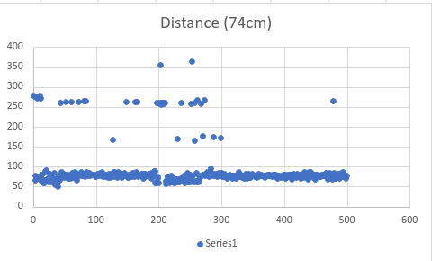
Symtom : it looks okay in close distance, but getting 400~500(cm) value on 100(cm)
How to do calibration?
And also it became hard to detect the tag…
Any other tips for using sma connector would be great too.
looks like the antenna is turned the wrong way, the radiating elements are facing the wall in your photo.
For ranging measurements you need to calibrate antenna delay for the device with the long cable, see: APS014 Antenna Delay Calibration.
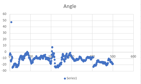
PDoA measurements with long cables will be tricky, as cheap coax cables are not phase stable. Any movement of the cables after PDoA offset calibration can alter the phase response.
Is the Angle PDoA or AoA? Can you compare with / without the long cables to see if they cause the variation.
From a stationary set of measurements you can use the mean as PDoA offfset (pdoaoff) to get the curve vary around 0.
Above, I tried antenna delay randomly to reach the actual distance.
I want to calculate to get initial delay like the document APS014 Antenna Delay Calibration that you sent.
How does this calculation work? There is not even scale.
The only thing I know here is Actual distance between chips : 7.914m
The PDoA offset is calibrated for the PDoA values, not AoA. At 0 degrees, take a set of a few hundred measurements and calculate the mean PDoA from that. Use this mean value as pdoaoff.
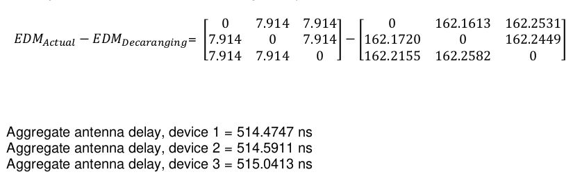
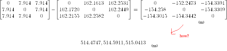
The values in the EDM matrixes are in metres. Distance between devices is 7.914m. When antenna delay is set to 0 for both devices, the reported range is around 162m.
My question is how does this matrix conclude in 514.4747, 514.5911, 515.0413 value?
There is no description on the document APS014 Antenna Delay Calibration
What I did was changing antenna delay every 100 ns to find value around.
But those 514.4747 looks very precise and seems like calculation result.
It is calculated by the algorithm shown in Figures 3, 4, and 5.
The antenna delay value is in chip units of 15.65ps. In free space, the UWB pulse travels 4.7mm (c*15.65ps) for every chip unit.
Example for two devices: we set the antenna delay to 0 and measure 162.16m, real distance is 7.914m, that means we have to compensate for the extra 154.246m in two devices or 77.123m in each.
(154.246m/c = 514.5ns)
((162.16m - 7.914m) / 2) / (c * 15.65ps) = 16 437.996
Now we can set the delay of 16438 in each of the devices and should measure close to the real distance.
In this example we are splitting the difference equally between the two devices. To get the accurate contribution of each device (and we don’t have a calibrated known device), we need a third device and do the EDM algorithm.