Hello,
I have built a C-Block with an output port of type “bit vector”. I have troubles to push any data to the output port within the C-script and always run into compiler errors. Has anyone an example using a bit vector (e.g. a simple counter)?
Best regards, Perry
Hi, Perry.
I’m not certain that I understand the question. Perhaps you could share some code demonstrating the problem?
–robert
Hi Robert,
thank you for your interest.
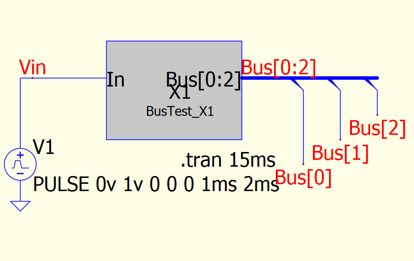
The top level schematic shows a simple counter and some circuit for visualization of the counter state.

When I generate the C-Source template I get the following variable declarations.
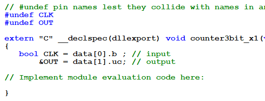
First I am confused to see that “out” has no type declaration. I tried various coding but always fail to address or write to my function output “out”. It always results in compiler errors. How can I write something into the output array?
Maybe I need to apologize to ask for something as stupid as this - at least it feels like. For sure I apologize for the quite stupid example. It simply would improve my schematics at work if I could connect C-Blocks with a bus. QSpice is such a beast in speed and with its support of C and Verilog its possible to simulate my whole system.
Best regards, Perry
Hi, Perry.
Hmm. If a bit vector is what I think that it is (a bit array in a struct packed into an unsigned char in this case), it wouldn’t really make sense to try to write it to a port (or to use it as a counter). If true, then the template generator probably is not assigning a type due to a programming oversight.
Unless you have some particular need to use that data type, why don’t use a standard integral or floating type and get past the first hurdle? If you are simply trying to get the output voltage to reflect the number of input clock cycles, one of the integer types will work.
Let me know how that goes.
Edit: OK, I see this is connected to a bus. I’ll have to research this further. If you declare it as unsigned char (at the port), you should be able to set bits and maybe then it would work?
Edit #2: Don’t you need to use “bus taps” to peel off the individual lines to the transistors? Yeah, I haven’t used a bus in QSpice and don’t see any info in the help. We might have to find someone more knowledgeable than me…
Edit #3: If you’re impatient like me, set the type for OUT to unsigned char& to force the compiler to finish. Assign 0xff to OUT. If QSpice doesn’t have netlist problems, then you can narrow down the bit order from there.
–robert
Hi Robert,
Generally I agree with you - it is no requirement for simulations to use bit vectors. When starting a project, it is most likely unnecessary ballast. But after nailing down the simulation results to real schematics with components and PCBs it can make sense.
Having the possibility to use bit vectors would make QSpice for me even more attractive.
E.g., I am using parts of my FPGA code (Verilog and C-code from the soft core) directly in QSpice simulation - unfortunately with the exceptions of arrays. One can use it as an enhanced test bench. I like to have the confidence to simulate what I have programmed. Changes done in the simulator can be pushed directly to the FPGA compiler and vice versa. What a neat solution…
Still, there are other ways to come over this topic. I see it a little bit like your very welcome project with the SPI and I2C interface. It’s handy. I like it.
You inspired me with your answer and I will now do further experiments.
I will keep you updated.
Best regards, Perry
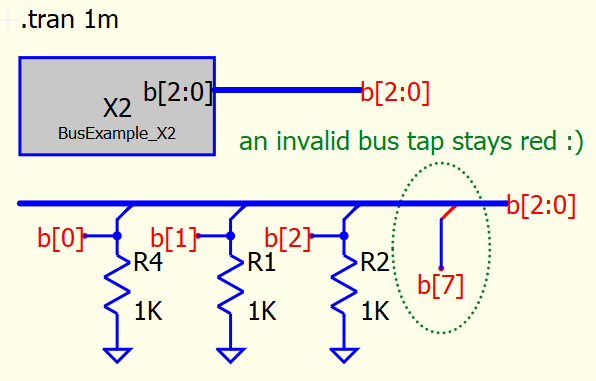
#Edit 1: I have used bus taps. Really good implemented into QSpice. E.g. if you have a typo then the bus tap turns red.
Thanks, Perry. Please do keep me informed. If you have a moment to instruct on how to set up the bus on the schematic side, I’ll play around with it. If not, I’ll poke at it more slowly. ![]()
–robert
To make a bus you simply draw a wire first.
Give it a bus net name like “b[2:0]”.
The thin wire will now turn into a thick bus line.
To pick something out of a bus you need to place a bus tap.
If you accidentally name a signal that does not exist it stays “red” and gives a compile error.
A bus will especially make sense in a hierarchical design. So let’s provide a very simple example.
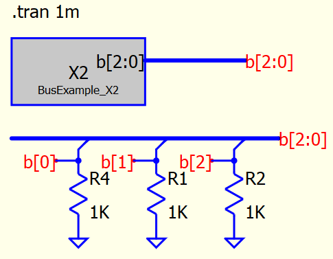
With the very simple inside of the hierarchical block:
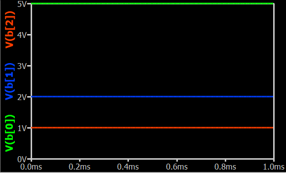
And for completeness the simulation results:
Best regards, Perry

Excellent. I’ll give it a shot. Thanks.
Hi, Perry.
Here’s what I’ve got so far:
The code:
bustest_x1.cpp (2.2 KB)
When I generated the template, the bus comes in as individual values in the uData array. I renamed and changed types to bools. I added code to map the bits from a counter to the bus. The outputs properly “count.”
Is that what you’re looking or do you need to use a bit array within the code? If the latter, that’s very easy to do with a wrapper function.
Let me know.
–robert
2 Likes
OK, added union to per-instance structure to allow treating counter as bit field. Maybe that helps?
bustest_x1.cpp (2.3 KB)
2 Likes
This is exactly what I was looking for and works perfect - thank you, Robert.
I completely overlooked to specify the array in the port name
and stubbornly entered the bus width in the “bit vector” dialogue.
Thanks that you spent your valueable time into my topic.
Best regards, Perry
Glad that helped. ![]()
FYI, Mike has fixed the template generation for “bit vector” port data types so that it no longer produces empty data type declarations in the uData array offsets.
–robert
Outstanding, how topics are handeled in this forum.
Thankful, Perry
2 Likes
Hi, Perry.
I just noticed that we have [0:2] and [2:0] in our examples. Does order matter? If so, which is correct?
Thanks.
–robert
Hi Robert,
That’s a good point. Let’s start to investigate hierarchical blocks first.
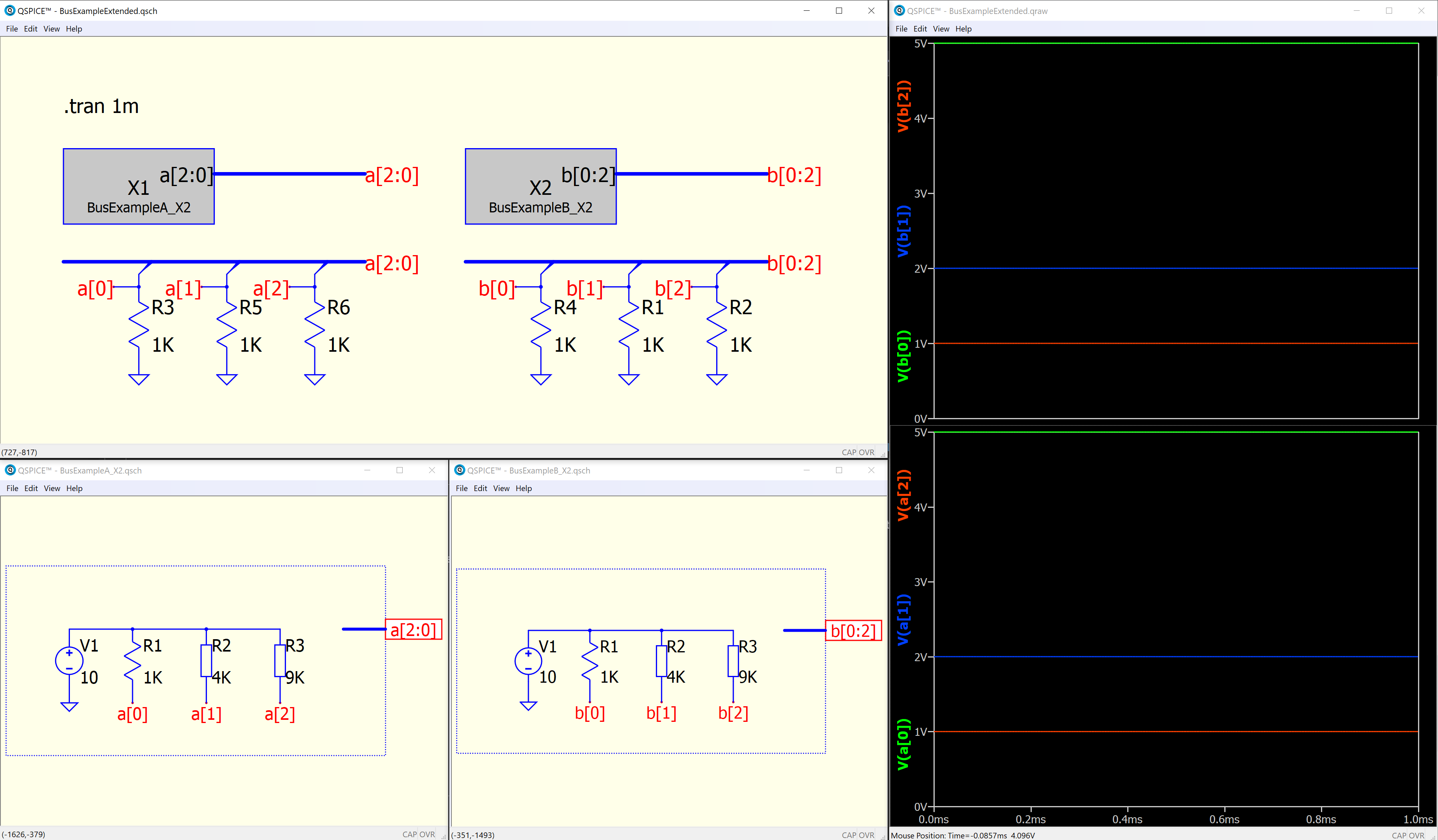
No matter how how you define the bus, [2:0] or [0:2], the signals are routed correctly. I think it is up to the users how to define it. QSpice performs excellent.
But one needs to be careful when mixing things up. In the next example the hierarchical block port is named with [0:2] and the connected bus is named with [0:2]. The voltages are rearranged! This is cool and what one would expect. On the other hand, I am lot’s of time in a hurry and will probably trap into this by mistake. ![]()

So half way is done. In the next session I will investigate this topic with C-Blocks.
Best regards, Perry
1 Like
My personal opinions is that, if bus is used, always maintain same order for everything, the hierarchical port name, bus name etc… in that order.
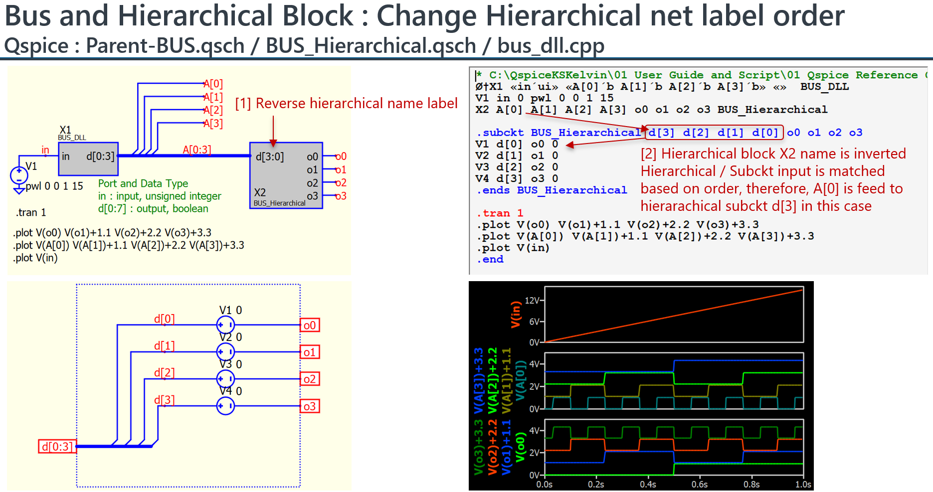
Netlist may help to understand bus in Qspice. From netlist, what you can observe is that, bus is to create a series of net name, with [1], [2], … in its name. This is not variable or array, but a series of net name. So, if you play with bus index, you actually play with a series of net name.
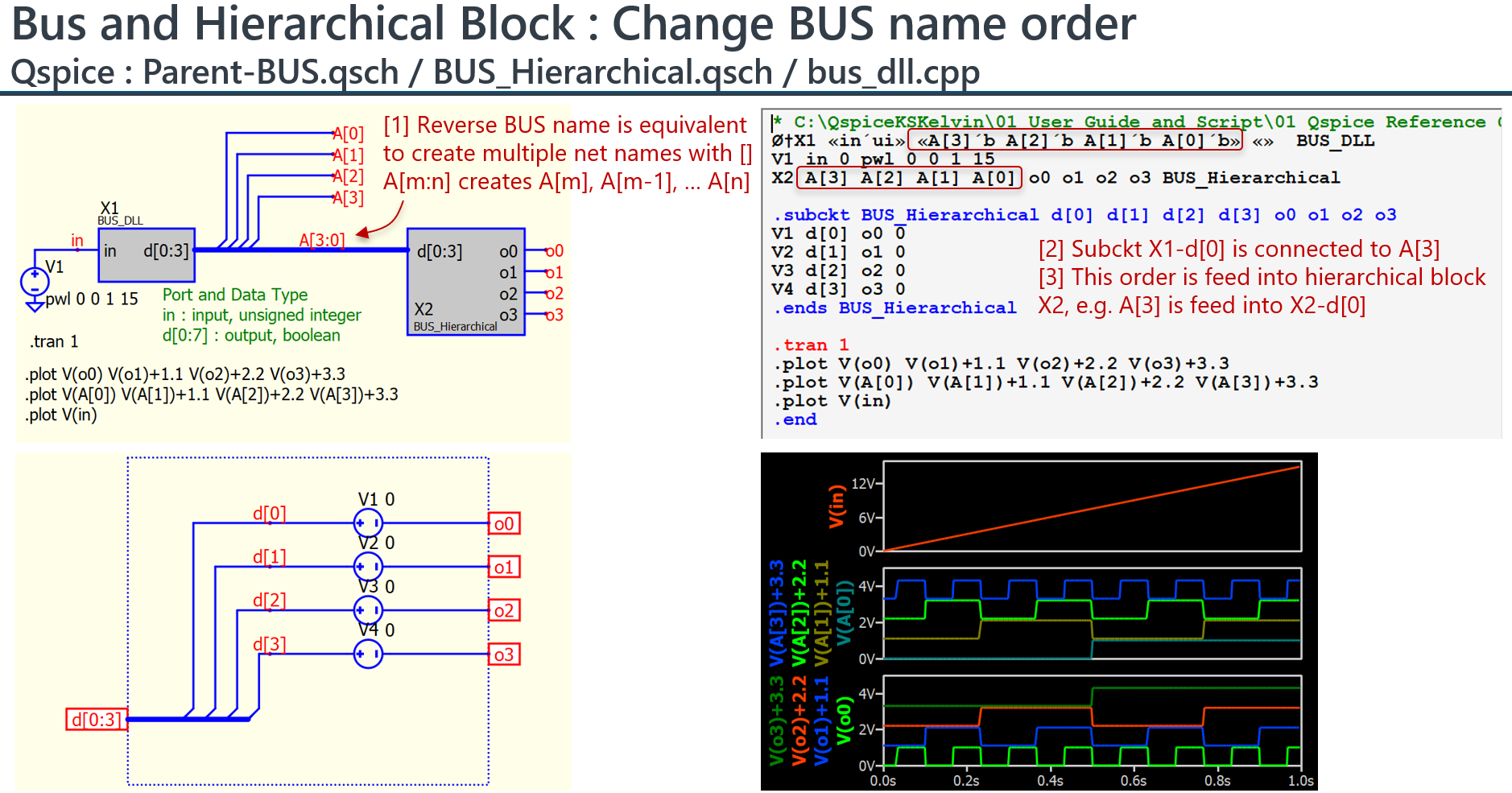
In spice, connection is defined by net name. In hierarchical / subckt, it ignore the name and match based on net name order. Therefore, in the 2nd and 3rd screen capture, if changes bus index or hierarchical index, will give you different results, and they are based on how spice is designed.
In short, you can define with DATA[0:7] or DATA[7:0], just maintain everything in that order. Prevent changing hierarchical port name without re-creating hierarchical block. It is possible to mess thing up if someone who are not familiar with all detail how hierarchical / subckt defines thing.
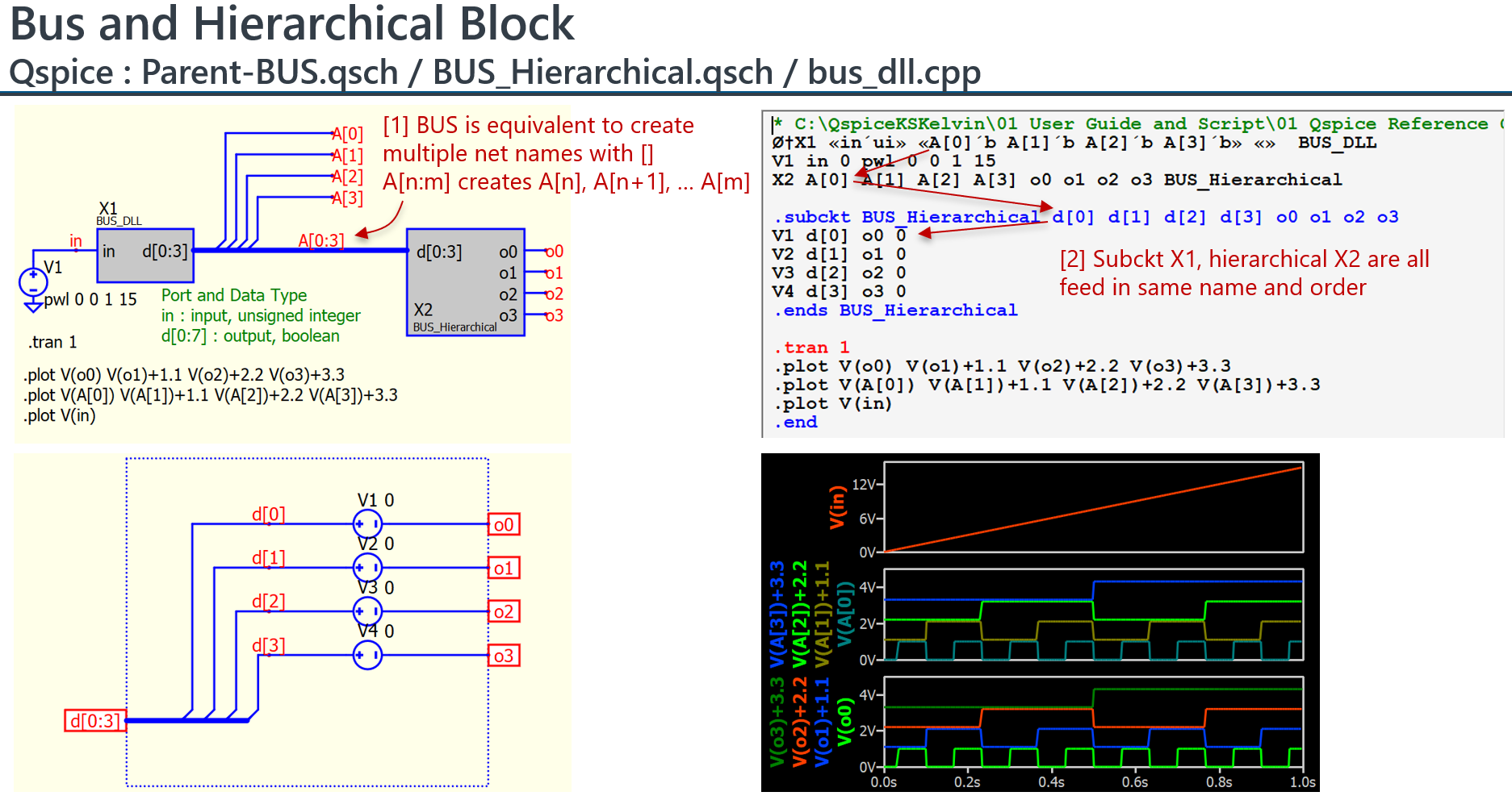
Example that change bus index or port index
2 Likes
As always documentation from KSKelvin is on another level and a pleasure to read. I totally agree to maintain always the same order for your bus stuff in a simulation. This should be the way to go and it will be much less error prone.
Since QSpice combines digital and analog world in a way I have never seen before, I would like to forget sometimes about its Spice background. When you feed a bus BUS[2:0] into a C-Block the automatic generated templated gives you a list with BUS_2_, BUS_1_, BUS_0_. Sometimes I have the feeling this is not what I want. In my C-Block I sometimes pack it in an array BUS[2:0] for better handling in the algorithm. I learned to deal with it and get along with it in my C-Blocks.
But especially when it comes to bit vectors and my pure digital stuff I would like to see something more handy. When you define a port of a Verilog-Block as a bit vector, the automatic generated template gives you already the bit vector BUS[2:0] into your code. That’s super cool. But when you bring it back to analog world it is not accessible as a bus in the schematic. It would be like a Christmas gift to me if this changes.
Best regards, Perry
3 Likes
Actually, I didn’t pay attention to bus until you work on this in this topic. In the beginning I also thought the bus feed some kind of matrix with index like array in matlab or python.
In spice, thing always more clear in netlist. So, just took this chance to demonstrate the use of netlist to clarifying thing. My feeling is that, bus in schematic is just an automatic way to define multiple net names manually. There is actually no “bus” in the netlist.
Following you guys post help me to understand more how thing work. ![]()