Upgrading from DW1000 to DW3000
Decawave’s (now part of Qorvo) DW3000 chip was released several years ago as an upgraded version of the DW1000. On the market, the price of the DW1000 has decreased, while the DW3000 remains expensive. Clearly, Qorvo is positioning the DW3000 as its primary product, maintaining the DW1000 for the existing market.
According to the “Interim Provisions on Radio Management of Ultra-Wideband (UWB) Devices” issued by China’s Ministry of Industry and Information Technology (MIIT) in 2024, effective August 1, 2025, the permitted frequency range for UWB operations will be 7163-8812MHz. This means all frequencies used by the DW1000 will no longer be allowed. In contrast, the DW3000 supports Channel 5 and Channel 9, with Channel 9 having a center frequency of 7987.2MHz and a bandwidth of 499.2MHz, which complies with MIIT requirements.
Over the past few years, many products were developed based on the DW1000, and now it’s time to upgrade to the DW3000.
I, too, spent a significant amount of time on the DW1000 over the past few years, developing a TDOA-based UWB positioning system. Recently, I undertook the adaptation work for the DW3000, and the migration from DW1000 to DW3000 was easier than I anticipated.
DW1000 vs DW3000
Broadly speaking, the DW3000 is an upgraded version of the DW1000. Here are some key differences:
- Supported Channels: The DW1000 supports Channels 1, 2, 3, 4, 5, and 7, while the DW3000 supports Channels 5 and 9.
- Standards Support: The DW3000 supports IEEE 802.15.4-2015 and IEEE 802.15.4z standards.
- PDOA Support: The DW3000 supports Phase Difference of Arrival (PDOA) for angle-of-arrival measurement.
- Power Consumption: The DW3000 has lower power consumption.
- Hardware AES: The DW3000 supports hardware AES 256.
- SPI Speed: The DW3000’s SPI interface speed is increased to 36MHz.
- Communication Rate: The DW3000 does not support the 110 Kbps communication rate.
Beyond the datasheet differences, during the actual code migration, I also observed some characteristics of the DW3000:
- The DW3000’s driver interface has undergone significant structural changes compared to the DW1000. It attempts to support various chip types, leading to a two-level abstraction of interface functions.
- DW3000 interface function names are largely similar to DW1000, but parameters may vary.
- The PRF (Pulse Repetition Frequency) used for transmission and reception is no longer set manually but is determined by the chip internally based on the Preamble Code used.
- Preamble Length has some changes, with new lengths of 32 and 72 added. Although many length macro variable names, such as DWT_PLEN_64/DWT_PLEN_128, remain unchanged, their corresponding integer values have changed. Additionally, the DW1000 uses 1 byte to store Preamble Length, while the DW3000 uses 2 bytes.
- The DW3000’s register layout has significantly changed. Many registers from the DW1000 have been merged and now exist as sub-registers within other registers.
- PAC (Preamble Acquisition Chunk) now includes PAC4, corresponding to Preamble Lengths less than 128. Interestingly, the driver code’s comment for DWT_PAC8 still states “PAC 8 (recommended for RX of preamble length 128 and below),” while DWT_PAC4 is commented as “PAC 4 (recommended for RX of preamble length < 127)”.
- The option to use non-standard SFD (Start of Frame Delimiter) has evolved into SFD Type, supporting more SFD types.
- PHR (Physical Header) can use a non-standard 6.8M rate, likely to increase PHR transmission speed.
- The DW3000 has removed the intelligent transmission function.
New features in the DW3000, such as STS (Scrambled Timestamp Sequence) and PDOA, are not present in the DW1000. As this is an upgrade of existing code, these parts will not be covered in detail here.
DW1000 API
The DW1000 driver is called DW1000 API, with the latest version being dw1000_api_rev2p14.
The DW1000 API is primarily designed for ST MCUs. If you are using a non-ST MCU, you may need to adapt some interfaces.
The DW1000 API is designed for operating a single DW1000 chip on one board (MCU).
In my previous programs, considering the need to support multiple DW1000 chips simultaneously, I modified the DW1000 API.
I defined a structure to describe a specific DW1000 chip, including its pin definitions, SPI definitions, and so on.
This added structure is roughly as follows:
typedef struct __DW1000_MODULE__
{
    uint16_t        Module_SPI_Prescaler;
    SPI_TypeDef* SPIn;
    GPIO_TypeDef* Module_SPI_Port;
    uint16_t        Module_SPI_SCK_Pin;
    uint16_t        Module_SPI_MISO_Pin;
    uint16_t        Module_SPI_MOSI_Pin;
    GPIO_TypeDef* Module_SPI_CS_Port;
    uint16_t        Module_SPI_CS_Pin;

    GPIO_TypeDef* Module_WakeUp_Port;
    uint16_t        Module_WakeUp_Pin;


    GPIO_TypeDef* Module_RSTn_Port;
    uint16_t        Module_RSTn_Pin;

    GPIO_TypeDef* Module_RST_IRQ_Port;
    uint16_t        Module_RST_IRQ_Pin;
    uint32_t        Module_RST_IRQ_EXTI_Line;
    uint8_t            Module_RST_IRQ_EXTI_PortSource;
    uint8_t            Module_RST_IRQ_EXTI_PinSource;
    IRQn_Type        Module_RST_IRQ_EXTI_IRQn;

    GPIO_TypeDef* Module_IRQ_Port;
    uint16_t        Module_IRQ_Pin;
    uint32_t        Module_IRQ_EXTI_Line;
    uint8_t            Module_IRQ_EXTI_PortSource;
    uint8_t            Module_IRQ_EXTI_PinSource;
    IRQn_Type        Module_IRQ_EXTI_IRQn;

    uint8_t            Module_IRQ_EXTI_USEIRQ;
    uint8_t            Module_RST_IRQ_EXTI_USEIRQ;

    uint8_t crystal_oscillator_trim;

    uint8_t rx_buffer[RX_BUF_LEN];
    DW_EVENT DWEvents[MAX_EVENT_NUMBER];
    uint8_t DWEventIdxIn, DWEventIdxOut;
    DW_EVENT dw_event_g;
} DW1000_MODULE;

typedef DW1000_MODULE* PDW1000_MODULE;
When I started the UWB positioning project, the most popular ST chip at the time was the STM32F103 series, and the MCU interface used the Standard Peripheral Library (STM32F10x_StdPeriph_Driver). Although ST had already released STM32CubeMX, it was not yet stable.
During that period, I attempted a small project using STM32CubeMX, but I found many issues (I even reported a bug to ST). Therefore, for the UWB positioning project, I continued to use the Standard Peripheral Library (STM32F10x_StdPeriph_Driver) to operate the MCU.
I added a parameter—a pointer to the instance of the DW1000 to be operated—to the DW1000 API interface functions, enabling support for multiple DW1000 chips.
Features of the DW3000 SDK
The DW3000 driver is called DW3000 SDK. After a certain version (DW3_QM33_SDK_1.0.2), the source code was no longer provided, only compiled library files.
The DW3000 SDK differs significantly from the DW1000 SDK. It accounts for supporting multiple DW3000s and also supports other chips similar to the DW3000.
Chip Differences
PRF
Both chips support 16M and 64M PRF. With the DW1000, you need to specify whether the chip operates at 16M or 64M PRF. The DW3000, however, does not require this.
In fact, the Preamble Code already contains PRF information. Preamble Codes 1-24 are supported, with 1-8 using PRF 16M and 9-24 using PRF 64M. Therefore, for the DW3000, you only need to specify the Preamble Code, eliminating the need for dedicated PRF settings.
Channel
The DW3000 only supports Channel 5 and Channel 9. Specifically, in register 01:14, the RF_CHAN field is a single bit: if 1, it indicates Channel 9; if 0, it indicates Channel 5.
Of course, using different channels requires corresponding adjustments to other parameters.
DataRate
The DW3000 only supports 850K and 6.8M communication rates, dropping the 110K rate found in the DW1000.
In practice, the 110K rate is indeed very low, and using it with the DW1000 requires special handling for many parameters.
In real-world applications, the 850K rate is more commonly used, balancing coverage range and communication speed. At 850K, our system’s coverage can exceed 200 meters, whereas at 6.8M, the coverage is within 30 meters.
Naturally, if a wide coverage range isn’t a strict requirement, using the 6.8M communication rate offers two benefits: power saving and the ability to accommodate more tags. A higher communication rate means each data packet occupies the air for a shorter duration, allowing tags more time to sleep and consume less power. Also, because each data packet is on the air for less time, more packets can be sent per unit of time, which translates to supporting more tags.
PreambleLength
The DW3000 supports more Preamble Lengths, dividing them into finer granularities. However, it’s important to note that the maximum Preamble Length in DW1000 is 1 byte, while in DW3000 it is 2 bytes.
    #define DWT_PLEN_4096 (0x1FFU) //!< Standard preamble length 4096 symbols
    #define DWT_PLEN_2048 (0xFFU ) //!< Non-standard preamble length 2048 symbols
    #define DWT_PLEN_1536 (0xBFU ) //!< Non-standard preamble length 1536 symbols
    #define DWT_PLEN_1024 (0x7FU ) //!< Standard preamble length 1024 symbols
    #define DWT_PLEN_512  (0x3FU ) //!< Non-standard preamble length 512 symbols
    #define DWT_PLEN_256  (0x1FU ) //!< Non-standard preamble length 256 symbols
    #define DWT_PLEN_128  (0x0FU ) //!< Non-standard preamble length 128 symbols
    #define DWT_PLEN_72   (0x08U ) //!< Non-standard length 72
    #define DWT_PLEN_64   (0x07U ) //!< Standard preamble length 64 symbols
    #define DWT_PLEN_32   (0x03U ) //!< Non-standard length 32
RxPAC
The DW3000 has added DWT_PAC4.
    //! enums for specifying Preamble Acquisition Chunk (PAC) Size in symbols
    typedef enum
    {
        DWT_PAC8 = 0,  //!< PAC  8 (recommended for RX of preamble length 128 and below)
        DWT_PAC16 = 1, //!< PAC 16 (recommended for RX of preamble length 256)
        DWT_PAC32 = 2, //!< PAC 32 (recommended for RX of preamble length 512)
        DWT_PAC4 = 3,  //!< PAC  4 (recommended for RX of preamble length < 127)
    } dwt_pac_size_e;
SFD
In the DW1000, there were only two options: standard SFD or non-standard SFD. In the DW3000, there are more SFD types:
    //! enums for specifying SFD Types and size
    typedef enum
    {
        DWT_SFD_IEEE_4A = 0, //!< IEEE 8-bit ternary
        DWT_SFD_DW_8 = 1,    //!< DW 8-bit
        DWT_SFD_DW_16 = 2,   //!< DW 16-bit
        DWT_SFD_IEEE_4Z = 3, //!< IEEE 8-bit binary (4z)
        DWT_SFD_LEN8 = 8,    //!< IEEE, and DW 8-bit are length 8
        DWT_SFD_LEN16 = 16,  //!< DW 16-bit is length 16
    } dwt_sfd_type_e;
PHRRATE
In the DW1000, the PHR rate could not be selected and only standard PHR rates were used. In the DW3000, the PHR rate can be chosen. Using 6.8M should significantly reduce the time a data packet occupies the air.
    //! enums for selecting PHR rate
    typedef enum
    {
        DWT_PHRRATE_STD = 0x0, // standard PHR rate
        DWT_PHRRATE_DTA = 0x1, // PHR at data rate (6M81)
    } dwt_phr_rate_e;
Transmit Power
The transmit power control of the DW3000 has also changed significantly.
While the DW1000 had only one overall power control, the DW3000 allows independent control over the power of four segments during transmission:
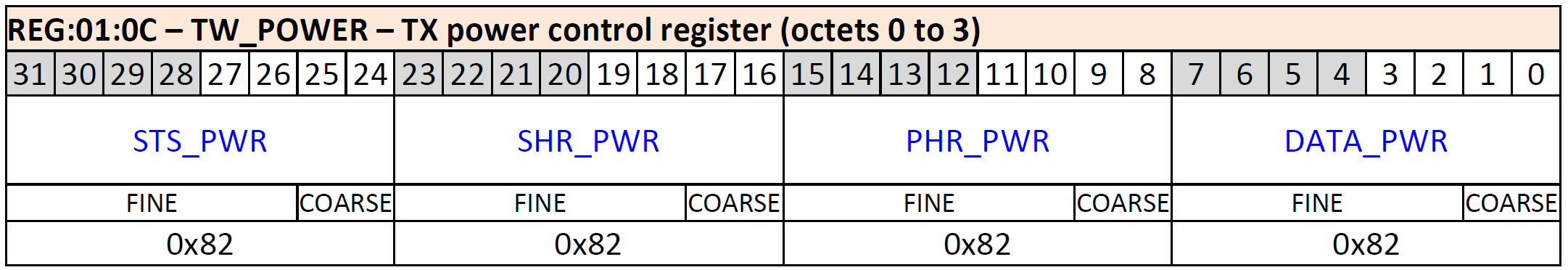
Each segment is 1 byte, with the lower 2 bits providing 4 levels of coarse control and the upper 6 bits providing 64 levels of fine control. Coarse control levels 0, 1, and 2 show significant changes, but the difference between 2 and 3 is minor, varying slightly for Channel 5 and Channel 9. The documentation suggests avoiding the 3rd level of coarse control, as it increases power consumption without much increase in power output.
In practice, if coverage range is a key consideration, sometimes even a slight increase in power consumption is worthwhile if the increased power ensures the desired coverage. Naturally, adhering to the power limits set by radio regulatory authorities is a prerequisite.
In actual use of the DW3110 chip, compared to the DW1000, I found that the communication distance of the DW3110 was shorter. This likely indicates a reduction in the DW3110’s transmit power, which also contributes to the reduced transmit current mentioned in the DW3110 Datasheet.
STS
STS is a new feature introduced in IEEE 802.15.4z; the DW1000 does not have this feature, but the DW3000 supports it.
    // Define DW3000 STS modes
    typedef enum
    {
        DWT_STS_MODE_OFF = 0x0, // STS is off
        DWT_STS_MODE_1 = 0x1,   // STS mode 1
        DWT_STS_MODE_2 = 0x2,   // STS mode 2
        DWT_STS_MODE_ND = 0x3,  // STS with no data
        DWT_STS_MODE_SDC = 0x8, // Enable Super Deterministic Codes
        DWT_STS_CONFIG_MASK = 0xB,
        DWT_STS_CONFIG_MASK_NO_SDC = 0x3,
    } dwt_sts_mode_e;
STS has four modes:
- Mode 0: STS is off.
- Mode 1: STS is added before the PHR.
- Mode 2: STS is added after the Payload.
- Mode 3: Only STS, with no data (no PHR and Payload).
To ensure compatibility with DW1000, Mode 0 (no STS) must be selected, as DW1000 does not recognize STS.
PDOA
PDOA is a new feature in the DW3000 that calculates the angle of arrival based on the phase difference of signals received by dual antennas. This will be covered in a dedicated article later.
Coexistence with DW1000
In some existing systems, a large number of DW1000-based devices may already be deployed. Replacing all of them with DW3000 would incur significant costs. Therefore, the coexistence of DW1000 and DW3000 becomes crucial.
I have tested and confirmed that DW1000 and DW3000 can communicate with each other when their configurations share common parameters. Common configurations mean not using parameters that the other chip does not possess. For example:
- DW1000 cannot use the 110K communication rate; only 850K or 6.8M can be used.
- DW3000 cannot use STS.
- Communication channels must use Channel 5/9.
- …
Since the DW3000 is more expensive than the DW1000, ensuring compatibility while not utilizing the DW3000’s new features feels somewhat regrettable.
This article concludes here.
I am currently offering UWB positioning solutions based on TDOA technology (https://en.uwbhome.top). By purchasing our solution, you can bypass the high-risk fundamental research and development phase and directly transition to production and sales. If you have any UWB-related project collaboration inquiries, feel free to contact me.