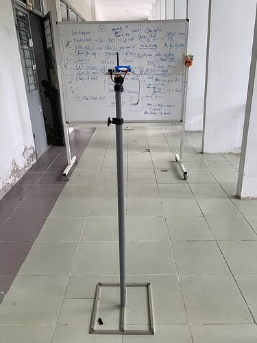
Hi everyone. I’m using DWM1001 for testing some NLOS environments. How does TWR location engine dwm1001 work? Does it use any algorithm to minimize errors in NLOS other than what APS006 wrote?
Hi @Vanperdung
NLOS is very tricky, complex and you need to know what with kind of NLOS you are fighting. In PANS it is set to work OK in the most of the cases but you need to test it in your scenario.
Cheers
JK
Hi @leapslabs
I am making my own RTLS using DWM1000, but when in NLOS environment, the measured distance is always about 50cm larger than reality. I tried using DWM1001 and it worked better so I wanted to find out how the algorithm fixed it. I changed to APS006 but the result is not better either. The environment I tested uses some thin wood panels placed near the Tag. Is there any way to reduce the error?
Hi @Vanperdung
I dont recall what was implemented by that time. But try to move the threshold a bit or read the accumulator and observe how the response looks like.
The wood panels should not introduce such errors. But try to maintain at least 10cm between device and wall.
Cheers
JK
This is my test. I put a plastic or wooden board between 2 devices, they are 5m apart. The results obtained are valid from 5.3m to 5.5m.
I’d estimate that hallway as being around 2m wide.
So if your signal was bouncing off the wall the path would be 2.5m forward and 1m to the side, bounce off the wall, another 2.5m forward and 1m back to the midde.
Total path length = 2 * sqrt(2.5 * 2.5 + 1 * 1) = ~ 5.4 m
In other words the ranges you are getting are about what I would expect if the direct signal was being blocked and you were picking up a reflected path.
Do you have any method to reduce the error?
Don’t put a big sheet of metal in the way? ![]()
Depending on how solid the obstruction is you may be able to get things to work in some situations. If you look in the CIR data there is a chance that you will see a slight peak from the direct signal but it’s not strong enough for the system to detect. If that is the case then in theory you could make a system that picks up the direct signal.
If you can’t see that earlier direct signal at all then all you can do is try a different frequency or more power and see if either of those give you any improvement. If that doesn’t work you’re into the world of analysing CIR data to work out the multiple reflection paths that give that result and then modeling the world around you to work out the locations that could result in those paths. Great if you are looking for a multi-year academic research project. Not so good for real world applications.
In terms of picking up weaker signals the simple way is to change the detection threshold registers to make the receiver more sensitive in an attempt to pick up weaker signals at the cost of a higher risk of false detects. Good luck working out exactly how the sensitivity registers work, their description is somewhat vague and doesn’t seem to always match the results you get out in terms of noise and threshold values.
Or you can pull out the CIR data every time and run your own peak detection algorithm that is more sensitive. But this is slow and a lot more work.
