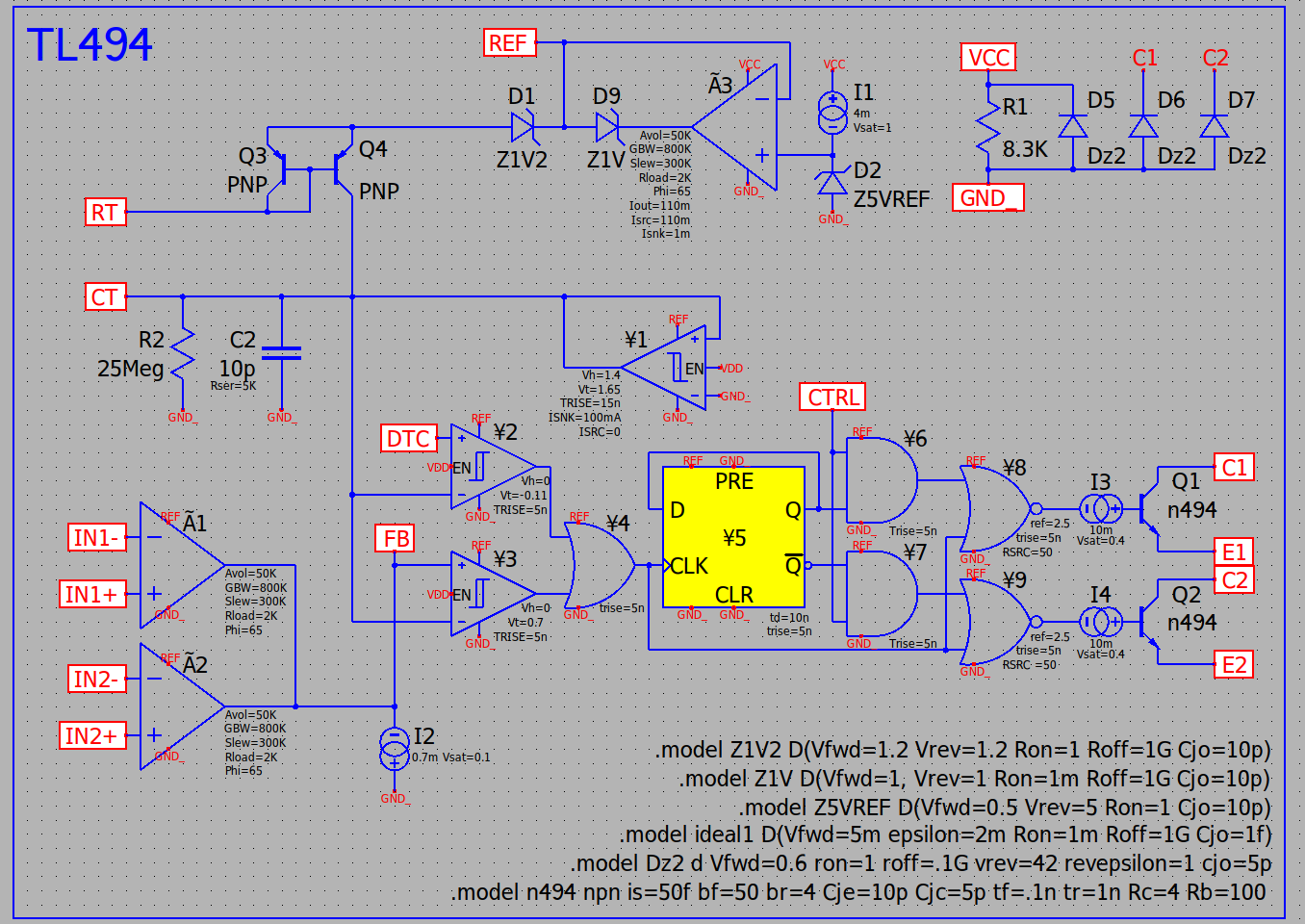
This is my take on it so far.
I want the chip to only function at all if there is power applied to it somehow. The current draw in the datasheet is nominal 6mA @ 15VDC and 9mA @ 40V, which maps to a 4mA || 8.3Kohms if I did the math right, not including the additional current draw of the oscillator, logic, and output drive.
I need to learn more about the BJT modeling and and better characterize the oscillator part on a breadboard. I will need to measure the voltage applied to the RT pin and determine the current multiplication factor to apply to the capacitor and fine-tune the current mirror. There are also some interesting dynamics that are noticable at the upper end of the frequency range. The dv/dt rate during the discharge can hint at the current I should use for the schmitt trigger device, and there are also some nonlinearities (BJT saturation?) that causes some anomolies in the ramp wave at the upper end of the supported frequency range.
The error amplifier GBP was increased to the values given in the datasheet. I have not adjusted the slew rate to match the real part yet.