i have some questions about the transmit power and the reachable transmit range.
The DW 1000 product brief says the transmit power ist -14 dBm or -10 dBm and the transmit power density is ← 41,3 dBm / MHz.
Am i right with the calculation (The 500 MHz and 1330 MHz is the Transmit Bandwith):
dBm = -41,3 dBm / MHz + 10 log (500 MHz) = -14.3 dBm
dBm = -41,3 dBm / MHz + 10 log (1330 MHz) = -10 dBm
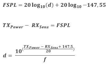
With this Transmit Power (TXpower), the receiver sensitivity (DW1000 Datasheet Table 6, p. 11, RXsens) and the free-space path loss (Free-space path loss - Wikipedia) it should be possible to calculate the transmit range:
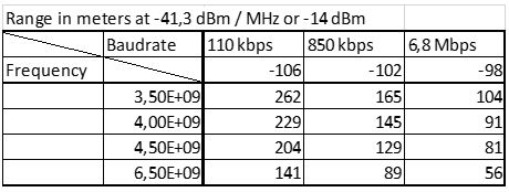
I calculated this with the four different center frequencies and the three differen baudrates. The results are listet in the following table.
Can you tell me if my calculation is correct and plausible or are there failures in my thoughts?
It seems pretty plausible to me, because the ~300m range from the DW1000 product brief are nearly reached with this calculation and also the ~60m from the DW1001 product brief are calculated right with the 6,5 GHz center frequency and the 6,8 Mbps baudrate.
The reason for my calculations is the transmit power densitiy limit in car mounted devices. The ETSI-Norm EN 302 065-3 limit the transmit power density to -53,3 dBm / MHz at car mounted devices. And i need to know the reachable ranges for my device.
It looks reasonable but you’ve missed out antenna gains and while the transmit may be 1330 MHz wide the receiver has a maximum bandwidth of 900 MHz.
The bandwidth will cost you around 2 dB. Antenna gain will give you around 4 dB assuming 2 dBi antennas at each end and good orientations.
Also this is all assuming no ground bounce, if you are around 2m off the ground at both ends then you’re going to start hitting ground bounce fades at ~80 m at the lower frequencies and shorter distances up at 6.5 GHz. If you’re closer to the ground then the distances go down.
the calculation was done with a bandwith of 500 MHz. So this should be fine.
I’m new to RF Communications, so i don’t know too much about the topic.
Does the antenna gain just amplifie the received signal or does it also increase the transmitted power from the chip into the air? If so, it would not be allowed to have a transmit power density / transmit power over -53,3 dBm/MHz / -26,3 dBm.
Could you please specify what you mean with “ground bounce” ?
I thought that the LOS-Signal should meet the receiver earlier than the multipath signal? So it should be possible to acknowledge the first path and the multipath signal with “estimating the signal power in the first path” section in the dw1000 user manual (4.7.1 p. 45), or am i wrong?
The antenna both increases the receive gain and the transmitted power. One of those rare situations where you benefit coming and going.
Generally the higher the gain the more directional the antenna. Antennas don’t create more signal, they focus it. A theoretically perfect omni-directional antenna would have a gain of 0. Just about all real world omni-directional antennas have a donut or toroidal shaped gain pattern, you get very little signal directly above or below the antenna and 1-2 dB of gain on all sides of the antenna. The other extreme would be a parabolic dish antenna which can have a gain of 40 dB but only in one very narrow direction.
You are correct, the maximum transmit power limits are normally in the direction of peak power so you don’t gain anything from the transmitted gain, if your antenna has 2 dB of gain you need to dial the power down 2 dB. My mistake there, sorry. But you do benefit from the receive antenna gain, this effectively increases your sensitivity, if you are pointing in the correct direction.
So ideally you’d have an omni-directional transmit antenna and send out as much energy as possible equally in all directions. And then have a high gain directional antenna for receiving pointed in exactly the correct direction. In reality you’re normally going to have omni-directional antennas on everything and just get a 1-2 dB benefit on the receive side.
Ground bounce is a special case of multipath. For most multipath the reflected signal path is multiple wavelengths longer, often hundreds or more, UWB is very immune to this.
However if you have two antennas mounted above the ground then at a certain separation you will hit a point where the multipath signal off the ground has traveled exactly 1/2 of a wavelength further than the direct signal. At that point the direct and reflected signals cancel out at the receive antenna meaning that there is virtually no signal power to detect. If there’s no signal power there isn’t a lot you can do about it, you can’t detect the signal because there is nothing to detect.
The wide bandwidth of UWB both helps and hinders this, because it’s wide you aren’t going to fade out all of the signal at the same time so there is always going to be something to detect but it will be weaker. The downside is that because it’s a wide bandwidth you’re going to see the effects over a larger range of distances than you would with a narrow signal.
For two antennas at the same height the fade distance is (4height^2 - wavelength^2)/(2wavelength)
So it is better to have an antenna gain for the receiving signal and lower the transmit power to hit the limits.
So if the anchor antennas are mounted at the ceiling and the tags are on the ground, the anchor should have an antenna wich is focused downwards and the tags antenna upwards to get better results.
Okay, i understand the problem of the ground bounce. But could this be just a problem for stationary systems? The tags are moving constantly through the area and the distance to the anchors is changing. The ground bounce effect shouldn’t affect the system.
Yes, if you know one side of the antenna will always face a wall/floor/ceiling then trying to find an antenna design that focuses energy away from that direction is a good plan.
That said in a lot of location system situations the horizontal distances are far bigger than any vertical separations you can achieve. At that point you basically need a horizontal plane pattern. That may mean that the antenna gain is terrible when you’re directly over/under something but in that situation the distance is so much less the antenna doesn’t matter as much.
The ground bounce will only be an issue at certain ranges so as long as you can live with occasional drop outs as you move through those ranges then it’s not an issue. However once you get over that distance keep in mind the free space model is no longer valid, signal strength will drop off more rapidly.
So if i know the pass through area of the Tags, then i could choose antennas which focuse the signal in this area.
I think i’m okay with some missing ranging measurements, because the tag should be fast enough to pass trough a ground bounce distance and reach the next anchor to communicate with. With your equation the distance where the ground bounce would be a problem gives me 173 m. I dont think that i will reach this distance.
Another hurdle where i’m actually struggeling is the preamble sent before the data. Maybe you could also tell me something to this, if not i open another topic.
After knowing the influence of the baudrate to the transmitted range, i decide to choose a lower baudrate for a higher range. The next hurdle is a mitigation technique named “low duty cycle” (LDC). With the LDC i’m allowed to transmit outside of a vehicle with -53,3 dBm/MHz. Otherwise it have to be -70 dBm/MHz or so.
The LDC allows a single transmit to be 5 ms long and a maximum transmit time of 50 ms in 1 s (5% of 1 s)
To figure out how long my transmit time is, i need to know the length of the data and the preamble send time. I struggle with the definition of the word “symbols”. What is a symbol? If the preamble is set to 2048 symbols, are this 2048 bits, bytes, …? And if i understand the user manual of the dw1000 correct, the preamble is not sent with the data baudrate (110, 850 or 6500 kbps) rather with 16 or 64 MHz.
For 2048 symbols (asumed to be bits) and a baudrate of 16 MHz the transmit time of the preamble is 128 us. Is this correct?
t = 496/499,2e6 * (2048 + 8) + (12 * 8 + 19) / 110e3 = 3,09 ms
t = 496/499,2e6 * (256 + 8) + (12 * 8 + 19) / 850e3 = 397,6 us
t = 496/499,2e6 * (64 + 8) + (12 * 8 + 19) / 6800e3 = 88,5 us
The results differ a bit from the tables results, but they are a good enough for me to estimate the timings.
Why is it for lower baudrates better to have longer preambles to reach the longer distances? Lower baudrate and higher preamble stretch the send time so much.