I’ve downloaded all the PDFs guides and will spend a bunch of time reviewing them. Thanks for the great Qspice resources.
Later,
Carl
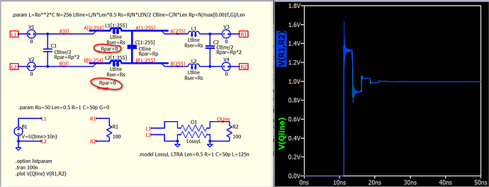
Update Lumped model with Rpar=0 for all inductors
TLine-Lumped-N=016-Rpar=0.qsym|attachment (3.5 KB)
TLine-Lumped-N=256-Rpar=0.qsym|attachment (32.5 KB)
Parent.TLine-Lumped-Rpar=0.qsch|attachment (43.6 KB)
The new information flow is like drinking from a firehose. I was trying to understand the B source equation while playing with these new models (compared to my lumped model). With some help from my good friend ChatGPT, I see that this is the Unit Step Function (Heaviside step function). I’ve been unable to find this reference in the QSPICE Help and the KSKelvin PDFs I downloaded. Where can I find help or references to stuff like this without resorting to ChatGPT?
Thanks,
Carl
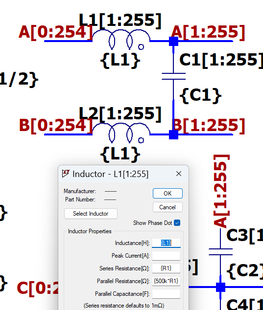
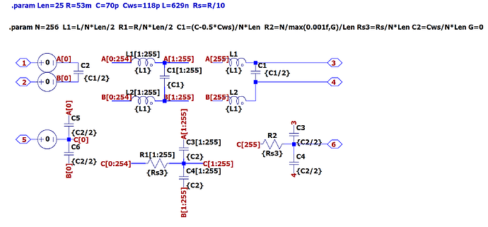
bordodynov, can you give a quick explanation of the operation of this circuit? I’m guessing that it is a method to chain 255 sections of this LC circuit (distributing the inductance into the center and shield of the coax). Is there any tutorial showing the process of developing this method?
Thanks,
Carl
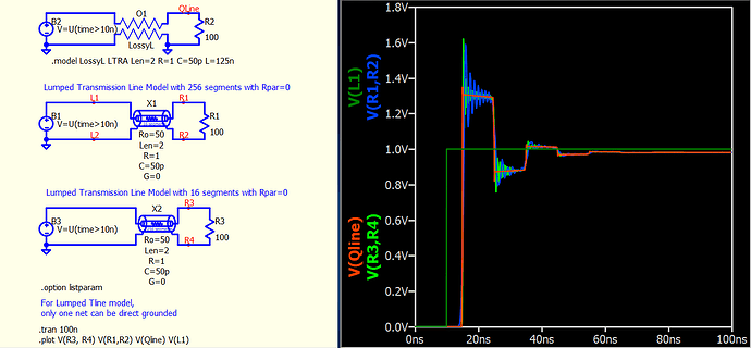
KSKelvin, your example waveforms show what I expected until I looked at the absolute (not differential) values at R1 and R2 (also at R3 and R4). The signal (in red) shows a non-delayed half amplitude signal appearing at the same time as the step transition. The T-Line signal and my lumped model signal show a line-length delay before the step change. Can you comment on the “instantaneous change” propagation down the line?
Thanks,
Carl
group vs Carl coax compares 01.qsch (48.7 KB)
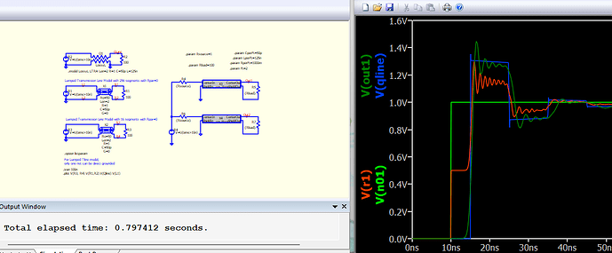
Update!
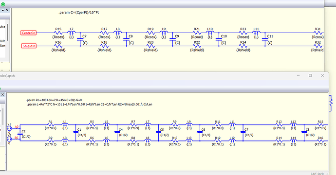
In working with the bordodynov bussed-matrix example (above), I discovered that the time difference I was complaining about in this post was because I had not split (and include) my inductance in both the top and bottom paths. This seems to explain my complaint/problem. Here is my circuit (top) compared to the bordodynov circuit (bottom).
Working out the details of this circuit, I back-derived the old relationship I remembered: Ro = Sqrt(L/C). I’m still hoping that there will be more documentation and tutorials to help people learn about the wonderful magic of QSPICE. Most of the brilliant QSPICE examples remind me of reading clever software that has had the comments removed.
Later,
Carl
I was designing a twisted pair model, not a coaxial cable.
I also developed a model of twisted pair in the screen.
Bordodynov, I’m guessing there may be significant differences between a twisted pair and a coaxial cable. Do you have any suggestions about a starting point for a coaxial cable model?
Thanks,
Carl
The coaxial cable is not symmetrical. It should not have lower inductances. Only resistances and not the same as in the upper circuit.
I wrote this up recently, see if it makes sense.
How to use SPICE transmission lines.pdf (803.7 KB)
I’m getting more practice with arrays and buses while experimenting with coaxial cable approximations. It seems that the arrays need to have 0V sources between the bus and the port to the parent schematic. Is there any documentation about this need? I thought the hierarchal structure would take care of the necessary aliasing. Is that not the case?
. . . and another array question: Is there a way to make any of the array indexes a replaceable parameter?
Thanks,
Carl
Purpose of 0V source is to assign different node name for the same node, such that your node name in hierarchy doesn’t have to be A[0] and B[0] but can be more meaningful.
I don’t see official document of bus or array component. Possibly this is a tradition that community document the undocument feature in the spice program by Mike. ![]()
Undocumented LTspice - LTwiki-Wiki for LTspice
I don’t see any method to set array indexes as a parameter. It is the schematic GUI handle the processing of array indexes, as if you change array indexes, you change the generated netlist. Therefore, the array indexes behave is not determined by Qspice64/Qspice80 (the simulator), but the QUX.exe. (but .param is processing by the simulator)
It makes a lot of sense. A transmission line model in SPICE is a Two-port network - Wikipedia. This means that the current that enters through one terminal of a port must exit through the other terminal of this port. It also means that only voltages between the two terminals of the same port (but not between different ports) are defined by the model. Both properties are easy to visualize by imagining ideal 1:1 transformers (working all the way down to DC) in series with the ports.
I’ve created some coaxial cable symbols that seem to work as expected, learning a lot about QSPICE in the process. The models can be used where the DC connectivity of a piece of coax is useful, like a power and signal duplexer circuit or a coax-length pulse generator. I’ve attached some sample schematics, the symbols, and the symbol-source schematics. Feel free to try them to see if they are useful. Let me know if you have any problems, questions, or suggestions.
Thanks to all who helped me along the process,
CoaxLump5.qsch (6.1 KB)
CoaxLump20.qsym (3.5 KB)
CoaxLump50.qsch (6.1 KB)
Coax lengrh pulse generator.qsch (15.0 KB)
CoaxApproximationTesting.qsch (98.5 KB)
CoaxLump200.qsch (6.2 KB)
CoaxLump200.qsym (18.0 KB)
CoaxLump50.qsym (5.8 KB)
CoaxLump100.qsch (6.1 KB)
CoaxLump100.qsym (9.6 KB)
CoaxLump5.qsym (2.4 KB)
CoaxLump10.qsch (6.1 KB)
CoaxLump10.qsym (2.8 KB)
CoaxLump20.qsch (6.1 KB)
Carl
