I can not find any description of this device in the help. So, I find it quite difficult to use it. For example: I type L = 700u as attribute. What have I declared now? Is it L primary or secondary and which of the primary or secondary? How are the turns defined?
Thank you for helping me!
You asked about Transformer3 (4 windings)… well, let’s first confirm 2 windings case.
Do you know these are equivalent?
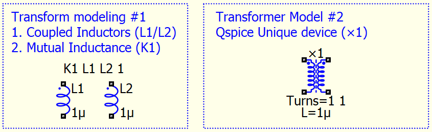
To answer your question, in short, for multiple winding ×-device, L defines inductance between PRI+, PRI- winding. As turn ratio of all winding are determined at Turns, other windings inductance is the result of this L and Turns, and you no longer needs to define it.
Simple math is that
Inductance of winding #1 : L1 = AL * N1^2
Inductance of winding #2 : L2 = AL * N2^2
Inductance of winding #n : Ln = AL * Nn^2
where AL is nominal inductance, Nn is no. of turns of that winding.
Transformer is winding into same core, therefore, AL is same as all windings.
As a results : L1/(N1^2) = L2/(N2^2) = Ln/(Nn^2)
Therefore, given L1, L2, turn ratio N2/N1 can be calculated.
OR given L1 and turn ratio, L2 can be calculated.
Legacy method (mutual inductance) is to define transformer by given L1, L2
Now, Qspice ×-device allow to define transformer by given L1, turn ratio
I explained the basics of transformers in two of my guides:
- Entry guide: There are 2 pages that explain coupled inductors (mutual) and the ×-device.
- Device guide: Provides a more detailed explanation in the inductor (L) and transformer (×-device) section.
These guides can be downloaded from here.
Qspice/Guideline at main · KSKelvin-Github/Qspice
Thank you very much. They are really good. But it does not answer my question: The Transformer3 has two primary windings and two secondary windings. One can not see where the primary and where the secondary side is. L seems not to be the inductivity of a primary winding. It seems to be the double for one primary winding. The turns Turns=3 1 1 3 is a 3 to 1 voltage from the primary (left) to the secondary (right). Strange sequence. These are the things I am asking.
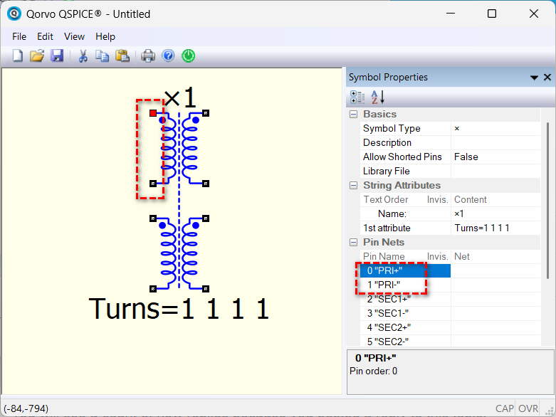
Right-click to Show Symbol Properties, then click the Pin Name to highlight its location. This is how you can differentiate the winding.
OR, download my custom symbols library (Qspice/Symbols-KSKelvin) as I added labels to describe the winding for the ×-device. You can customize the labeling or pin arrangement by creating your own version of the ×-device.
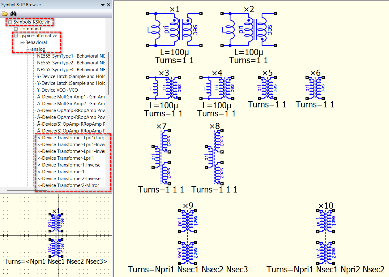
Well, primary or secondary is just a name. In 4 windings, they are all in coupling. Are you building a push-pull configuration (two primary and two secondary)? If you don’t like the standard Qspice version (i.e., ×9 in the above post, one primary three secondary, drawing best fit to flyback), I highly recommend downloading my custom symbols and using the ×10 version. For that one, I particularly rearranged the pins and labels to fit into a push-pull drawing (it will use Turns=3 1 3 1 instead). But again, these are just ways to manage the symbol. In Qspice, it runs in the netlist, and the syntax of the ×-Device is…
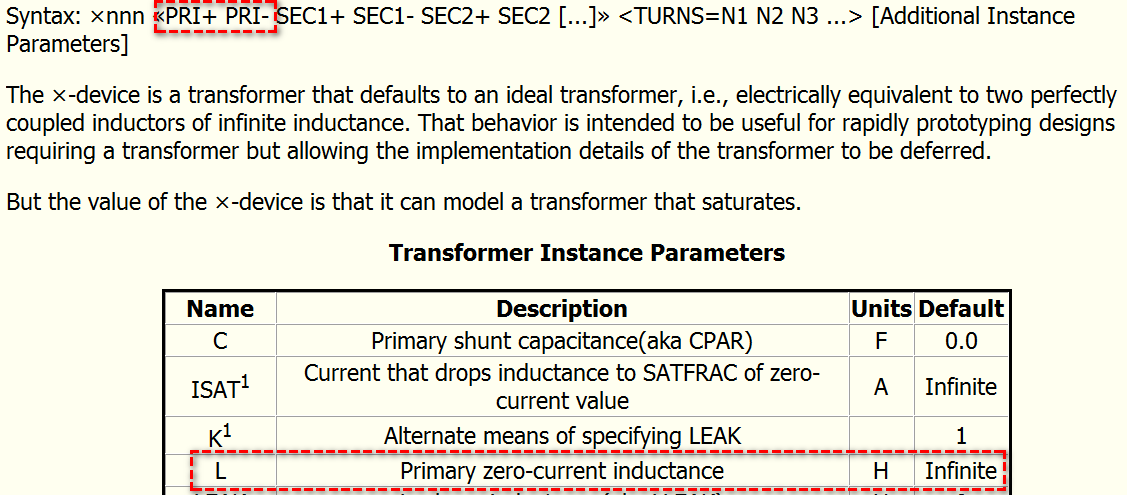
Syntax: ×nnn «PRI+ PRI- SEC1+ SEC1- SEC2+ SEC2 […]» <TURNS=N1 N2 N3 …> [Additional Instance Parameters]
L is always the inductance between the first two nodes, and Qspice (like most people) defines it as the primary. Essentially, it refers to the first two nodes.
The ×-device is very special; it is an ideal transformer, which means that it can precisely follow the N1/N2 = V1/V2 = I2/I1 formula if L is not specified. Native ideal transformer model cannot be found in Pspice or LTspice.