Hi all,
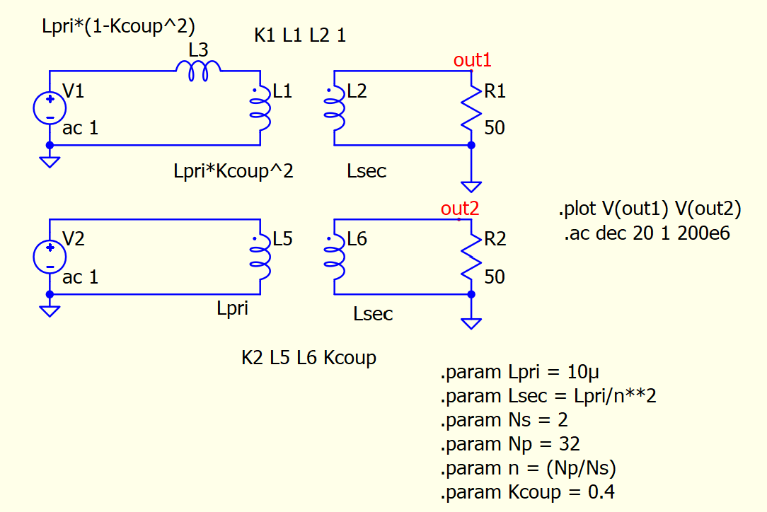
Regarding Qspice- Device Refereence Guide, I built a simulation below.
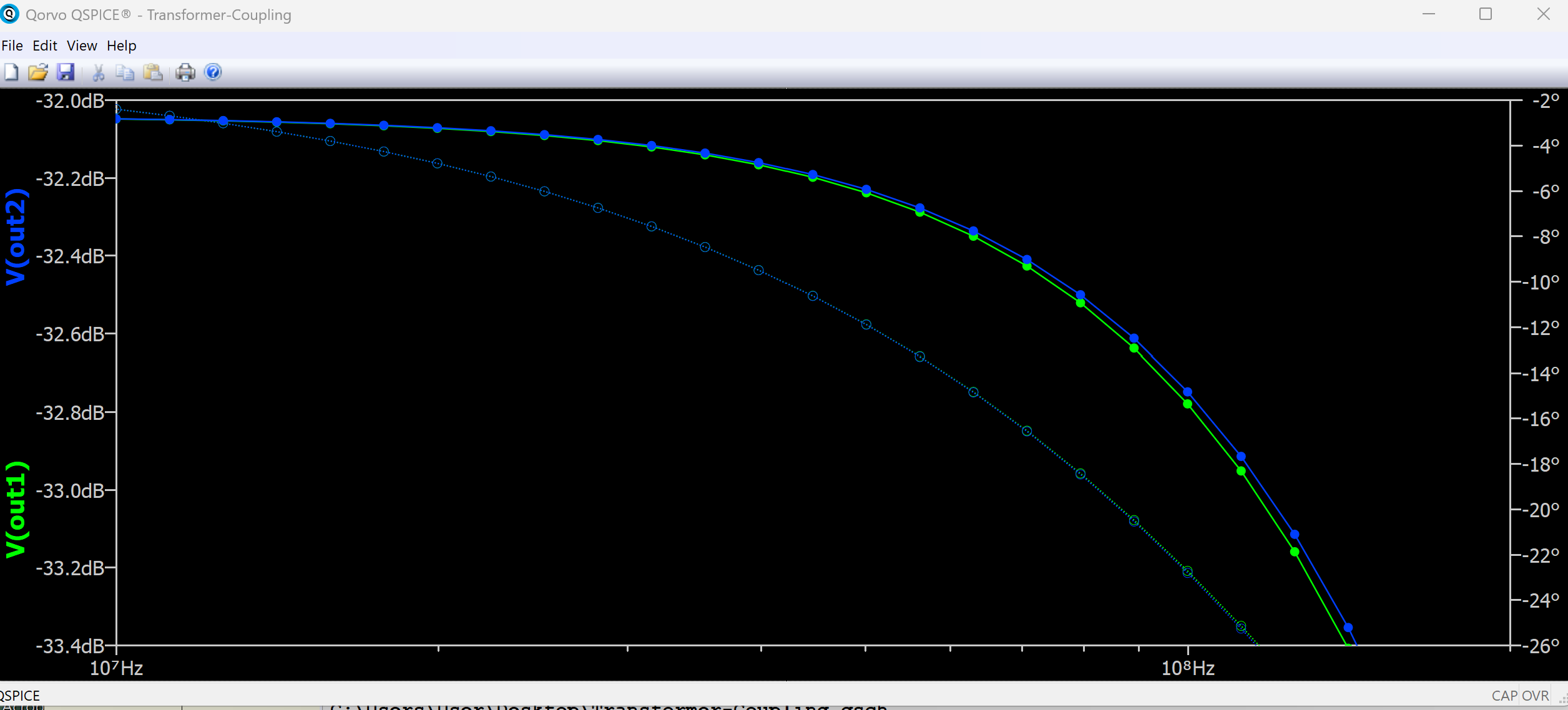
There is some discrepancy between two graphs in the high frequency range. Is it normal?
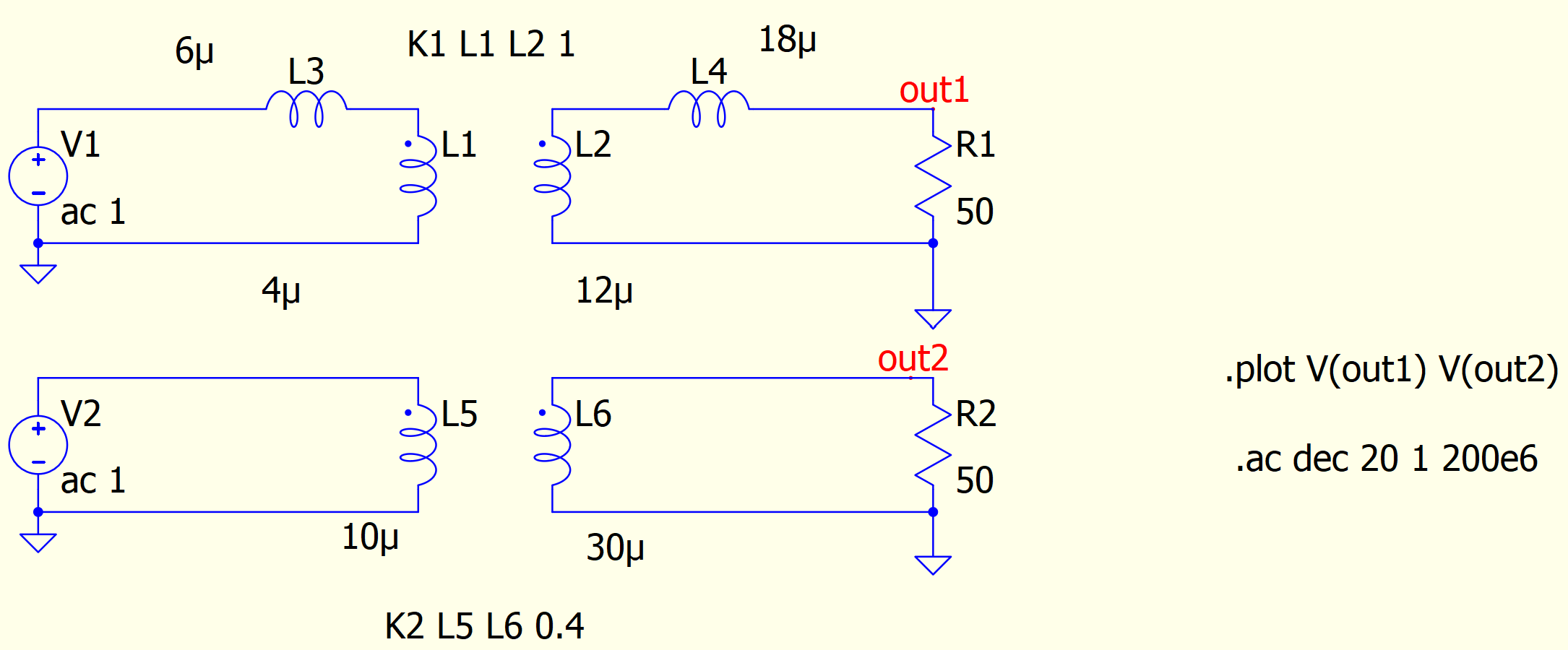
In addition, I came across this post How to simulate a transformer in LTSpice with custom turns ratio and inductivities? - Electrical Engineering Stack Exchange
So, I did the simulation below. The results are matched. Do we have to take care of the secondary leakage? because I do not see secondary leakage in the example above.
youre right, leakage on physical magnetics exist on both primary and secondary. thus, must be modeled as if you have series inductance on primary and secondary.
anyway, assuming Llk << Lm, for simplification its common for most people to reflect all the leakage to be only on the primary side → Llk(total_primary) = Llkp + Llks*(Np/Ns)^2
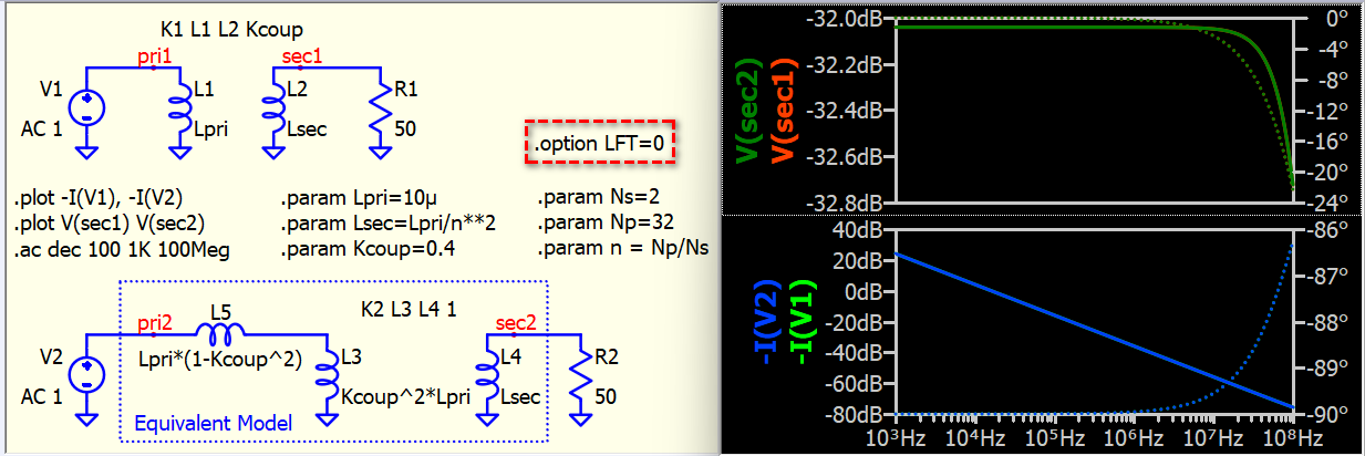
add .option LFT=0
Rpar of the inductor is causing such deviation; therefore, we have to remove it from the equation.
Filter Simulation don’t work - QSPICE - Qorvo Tech Forum
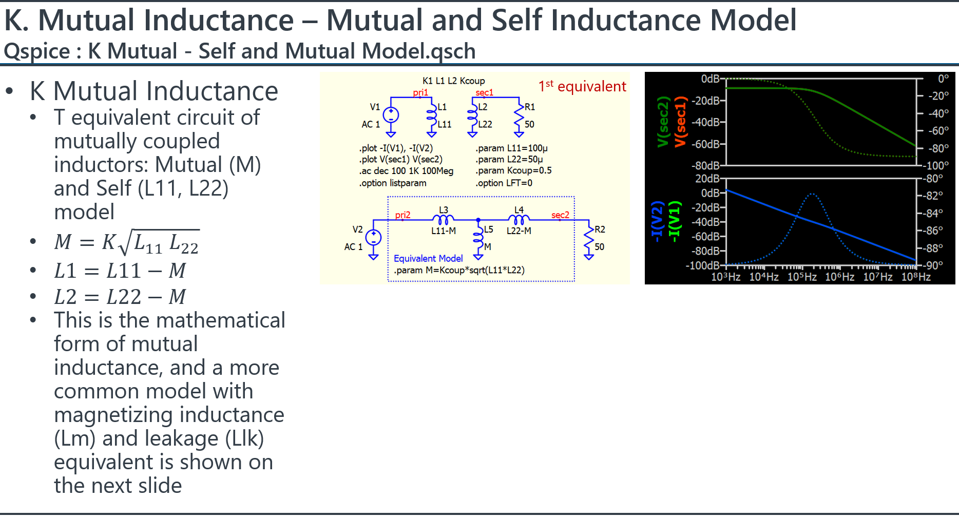
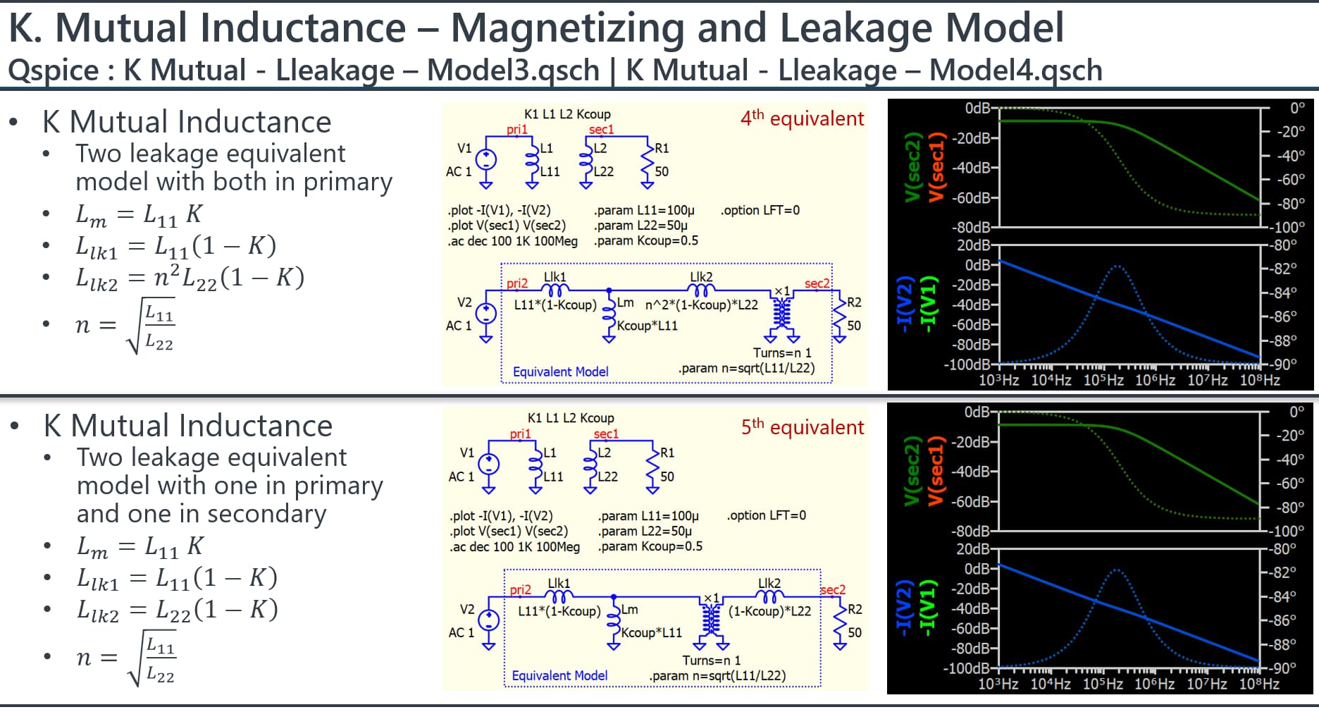
@mingche_joe @physicboy I have to be very humble in this topic; after all these years of studying, I am still not sure if the mutual inductance model (K coupling with L11, L22) includes secondary leakage effects or not. Well, let me show you something interesting. Here are five equivalent circuits that can produce identical results in .ac analysis for input current and output voltage in bode plots. The fifth one is a model with both primary and secondary leakage inductance, while the fourth one is the transformer model that PSIM also uses in its ‘1-ph Transformer’, which to describe secondary leakage but with its value moved to primary only.
Professor Sam Ben-Yaakov explains that all equivalent models can be used. It’s very interesting; people tend not to believe it, and he created this video to convince the unconvinced.
Transformer leakage in LLC converters - YouTube
In my understanding, the most correct (or at least most intuitive) equivalent circuit is your model <5>.
*I know you have go through the length to proof 1~5.
My reason being, is leakage in magnetic world is defined as free stray magnetic field that is just chilling within the winding window (instead of being in the core and getting nicely couples to each other winding. And for it to happen, there should be somewhat equal contribution of leakage from the primary and secondary side as the total MMF through the winding length is zero.
→ I kinda feel I am writing nonsense here…haha
→ another note is, I make this kind of realization when I worked on 1:1 turn ratio of wireless charger coil, and I need to match the Ansys Maxwell and measurement with LCR. By which I come up with the equivalent circuit you draw on <5>, then comeup with proper Llkp, Llks, and Lm ,measurement and separation method.
This is reason that Prof. Sam made those videos.
But I agree <5> is more intutive and direct in determining each parameters, as in real measurement, we measure Lm, Llkp, Llks etc… instead of directly having K.
I typically model transformers with K=1 (or with Lm and an ideal transformer) and then add external leakage inductance, resistance, and stray capacitance. This approach allows me to analyze the current in each element. From my perspective, using Lm and an ideal transformer is the best method as it enables me to differentiate the current flow into magnetizing and from primary to secondary (mutual inductance method merge this two current), which is essential for studying the circuit’s operation.