Hello,
I would like to use TQP7M9106 in my project for 2W, 500-1000 MHz amplifier.
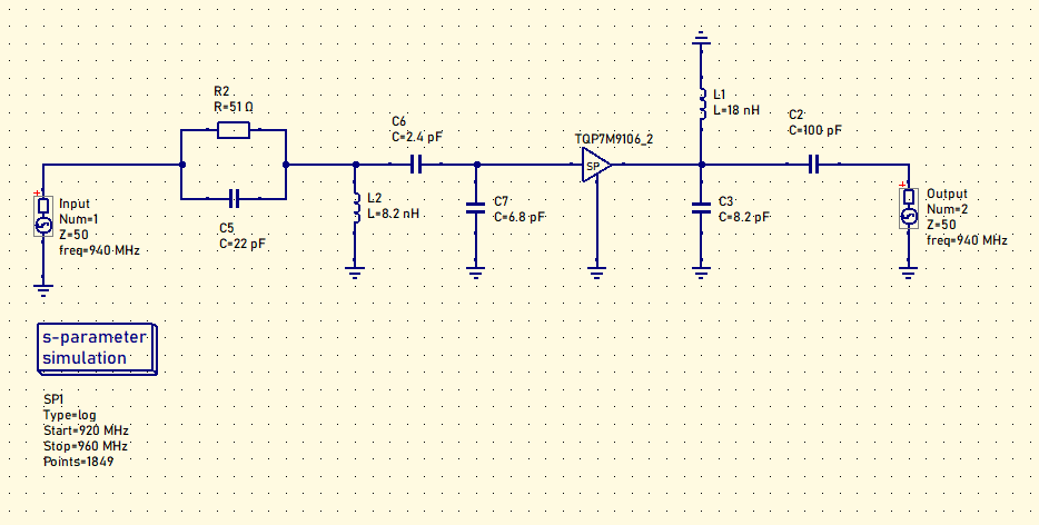
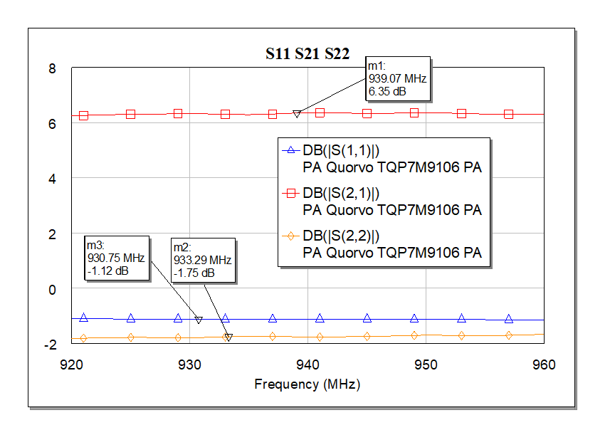
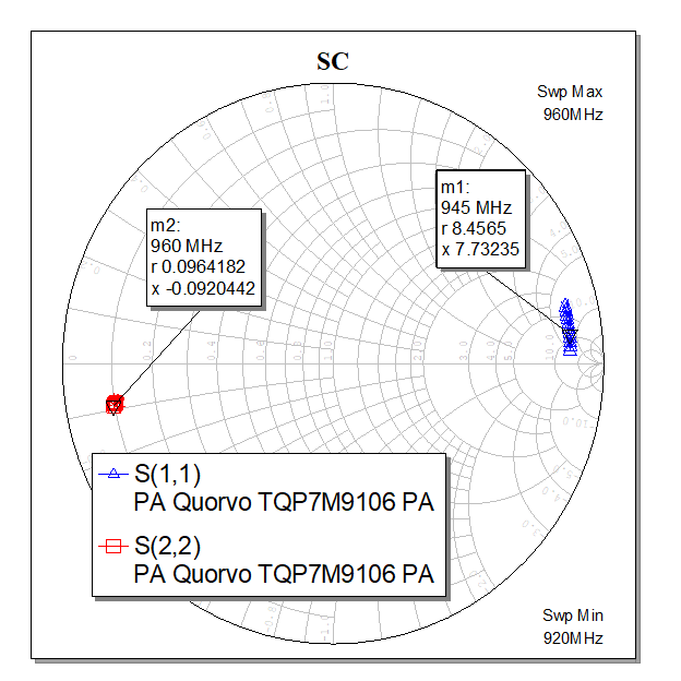
Firstly I checked datasheet schematic (TQP7M9106-PCB900) for 920-960 MHz and have a issues with results.
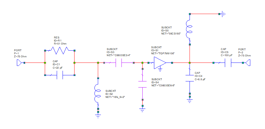
We think s-parameter file for TQP7M9106 is not correct. We check using both uSimmics 5.8 (with ideal components) and AWR Design Environment V15. (with s-parameters components)
TQP7M9106 S-parameters from TQP7M9106 - Qorvo
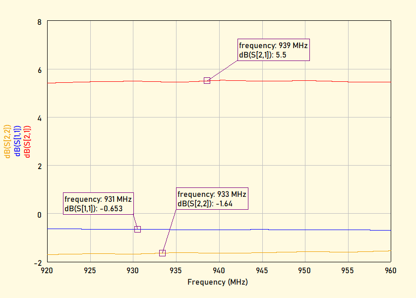
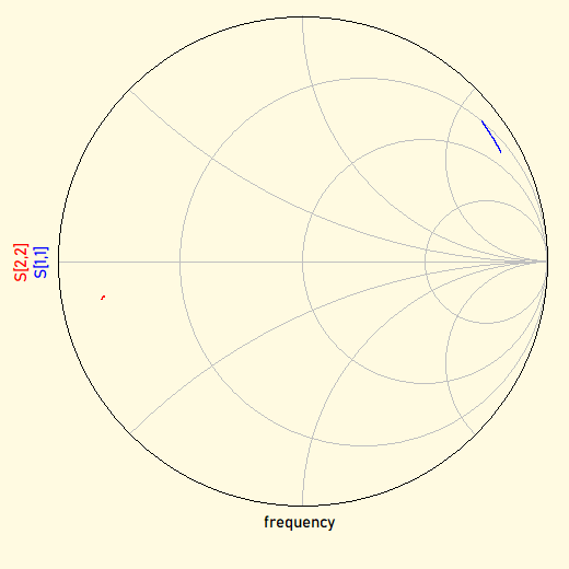
Both modelling results are very similar and not expected.
Probably TQP7M9106-PCB900 schematic\BOM is not correct or TQP7M9106 s-parameters is not correct.
I would be gratefull for any comments, ideas and recommendation.
Hi,
The TQP7M9106 datasheet provides a list of critical component placement locations for this tune on page 4:
Center of C8 to TQP7M9106 (U1) device package is 243 mil (11.7º at 940MHz)
Center of L5 to TQP7M9106 (U1) device package is 452 mil (21.8º at 940MHz)
Center of C9 to TQP7M9106 (U1) device package is 275 mil (13.3º at 940MHz)
Center of C2 to TQP7M9106 (U1) device package is 355 mil (17.2º at 940MHz)
These should be included in your simulations. There is a reference design for 450-800MHz, see attached. TQP7M9106 450-800 Refrence Design Appnote.pdf (252.5 KB)