I don’t think the problem is your method of importing the model.
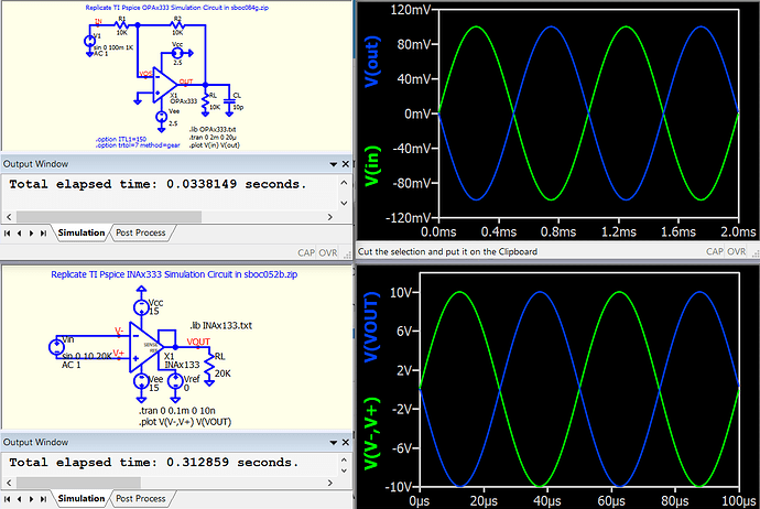
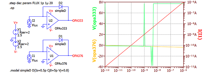
TI’s model for the OPA333 works in Qspice in only small set of applications, that happens to include their example file.
-
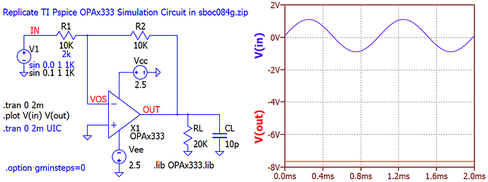
If we use an offset of 0.1V sin 0.1 1 1k so the initial voltage is nonzero, Qspice finds an stable operating point with −7.5-V output.
We can skip finding the operating point with the option ‘Use Initial Conditions’ (UIC) but then we need to specify an initial voltage with ic= on each capacitor . . . or just let Qspice use the default zero voltages and try a transient simulation from there. After a brutal first 10 µs, the transient luckily settles on a reasonable solution.
-
If we increase the gain from 1× to 5×, the output clips, and at 0.4 ms when the circuit begins to recover from overload, Qspice gets stuck in small timesteps.
Analysis
OPA333_expanded.qsch (221.0 KB)
TI’s model OPAx333.lib contains no transistors nor diodes. It matches the experimental results with a behavioural model, using Rs, Cs, linear G-devices, nonlinear B-devices with I=limit(x, upper, lower) and switches.
All the gain is in the first stage, later stages gain 1.0, probably so signals can be easily interpreted as the effect they would have on the output; this means intermediate signals can go beyond the power rails, as the signals are scaled up from the real voltages on wires.
The model comprises
Error Integrator – Active Filter – Output Buffer
The Output Buffer is clipped by comparing its output voltage with the power rails, and applying a correction to its input to clip the output.
When the Output Buffer is clipped, the Error Integrator continues to charge its output capacitor in a direction to correct the output (as if it could overcome the clipping). We have integrator windup.
There is a BLOCK_DC switch that acts like a pair of Zener diodes between the corrected input to the Output Buffer and the Error Integrator output. This BLOCK_DC conducts when the integrating capacitor is outside ±10V from the clipped output – thus allowing just some integrator windup, presumably to match the experimental recovery from saturation.
That BLOCK_DC switch, when closed, is positive feedback around the active filter. Due to rounding errors entering the Rs and Gs, the low-frequency gain of the active filter is 1.0006, so we have the potential for positive feedback with amplification.
With 0.1 V input, the Error Integrator will work to charge its capacitor to AvOL×0.1V = 300 kV. The G-devices have no problem with 300 kV, and the Active Filter output is approaching 300 210 V. The clipping circuit will correct that high voltage, with some delay, but the clipping circuit has a limit(x,upper,lower) function that restricts it to a reasonable correction, negligible compared to 300kV.
BLOCK_DC shorts, to try to bring the capacitor within 300 210 V ±10 V, which is larger than 300 kV. The voltage grows until other nonlinear devices stop it.
The Gmin-stepping method of finding the operating point happens to find a solution where the integrating capacitor has 112 886 kV, amplified to 112 967 kV by the Active filter, but then reduced back to 112 886 kV by the clipping circuit.
We can avoid this operating point (by not using Gmin-stepping, reducing the Active Filter gain, ic=0 on the integrating capacitor, or otherwise).
But even then, if we increase the gain or the input such that the output clips in the transient simulation, the simulation stops due to the timestep going to zero.
The switches in BLOCK_DC have Ron=10mΩ Roff=1GΩ with a transition voltage of 10 mV. So in the transition SPICE is computing a resistance from 1e9Ω to 1e-2Ω so one can imagine it may be difficult to coding the maths for this transition using 14-digit IEEE double-precition registers. NgSPICE recommends a ratio below 1e12, or else adjusting some options. Ron=1Ω here lets the simulation continue.
The BLOCK_DC function should be done differently. Preferably, the Error Integrator itself would slow its rate of charging the integrating capacitor as the voltage on that capacitor approaches the power rails.
Moral
I wasted a lot of time (which have time at the minute) reverse-engineering the Rube-Goldberg device that TI assembled over the years to match experimental data. But now I know what I’m missing if I forego a TI model that doesn’t converge.
Often software helps to get useful work done.
Sometimes software distracts us from useful work.
Burr-Brown designed some nice amplifiers, so we should feel free to design using them, but might sometimes have to do so without a manufacturer’s SPICE model.


