Hi,
I can see these things in Symbol & IP panel for voltage:
But I cannot see these things for current in Symbol & IP panel…
Hi,
I can see these things in Symbol & IP panel for voltage:
But I cannot see these things for current in Symbol & IP panel…
To find the keyword for different kind of symbols…
Just try to press every keyboard buttons
For this one…just press “i”
In the case of current source if I press i nothing change, like it is in the case of the voltage source when I press v.
yep… I just noticed that as well… its not a thing for current source as pointed out by Kelvin in a DM
@Cornel ,
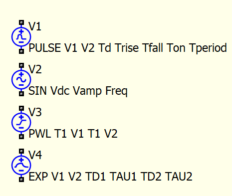
Someone (Mike?) created multiple symbol types for the different Voltage sources.
No one created a similar symbol set.
Having said that, you can create your own.
Note: The one current symbol is sufficient. All you have to do is supply the waveform type into the parameter.
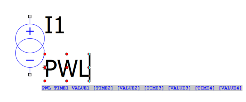
For example: I added a current source and started typing the “PWL” wave type into . QSpice will help with the remaining parameters for PWL.
The added symbols for the Voltage source is just a visual aid. The symbol itself is not of value in the simulation.
Len
I was going to write about it, I also discovered it yesterday.
@Cornel ,
I believe the reason for not allowing a a component value to be “0” is that when some math is performed on the circuit nodes, it is possible that a DIV BY ZERO might occur.
In reality a 0 ohm resistor is not really practical (the exception might be with super-conducting materials near 0K). A practical 0 ohm resistor is many times closer to 1 mOhm.
Instead of using the jumper method, if you use the same circuit under different configurations, you can use the step parameter method (ex: .step param R1 list 1n 100 1000). This allows you to create many sims of the same circuit with different values for one or more of your circuit components.
I use this all the time to get visual and quantitative results for RC, RLC and RL filters.
Len
Ah, Ipoma I think you want to refer to this topic (its not my topic) with what your wrote now: