Hello community,
so I am simulating a buck converter per App Note 1162 by International Rectifier. Specifically the example on page 20:
5.4 Design example of Type III-B compensator
When I run the numbers, and place the calculated compensator values, the simulation fails. However, if I add a series resistor of significant value (@KSKelvin also mentioned this in a previous post and got my previous buck converter to work), then it ‘works’. In a real world application with actual components, would the calculated compensator values actually work? Is the requirement of havinkg to add an inductor esr more of a QSpice oddity to force the converter to work - note the value that I added is almost 1 Ohm (!)?
Can someone offer insight how a ‘real’ buck converter would be made to work if the calculated compensator values are not working as expected.
Here is the buck converter in question. Note that I had to add a rather large esr value in order for the buck converter converter to work.
Synchronous_Buck_Converter_Compensator_Type_III_2z3p_Transient_Load_working_step_resp_4cap.qsch (40.5 KB)
Thank you for any insight that you may provide.
The compensation network can work without ESR in L1 if you disable the LS FET and use a diode instead. LS FET is a bidirectional switch in a synchronous buck converter, sometime in related to that seems messing thing up in your case.
Synchronous_Buck_Converter_Compensator_Type_III_2z3p_Transient_Load_working_step_resp_4cap.qsch (41.3 KB)
Thank you @KSKelvin for replying to my post and offering a potential workaround.
So, if I am simulating a synchronized buck converter, I am forever required to add an esr resistor of significant value otherwise I have to operate it in asynchronous mode with a diode?
How about if this had been a real circuit? Is this a QSpice bug or shorcoming?
I didn’t go through your circuit in detail. May be this only relate to this compensator and how it setup. It seems to me your circuit can start with a LC resonant with the help of LS FET. And the ESR of L actually to damp that.
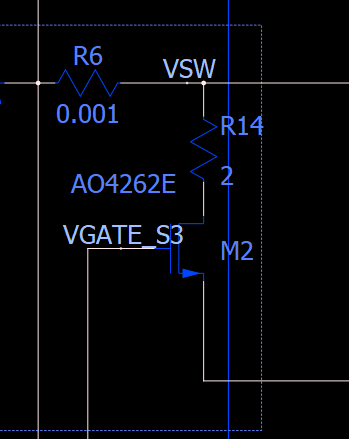
If I add a series resistor to the FET, of also significant value (2 Ohms), then it works fine. This is a bit odd tbh.
It is same damping path when LS FET is ON that why same effect as your ESR in L1.
If the esr is placed AFTER the inductor, only a 1 Ohm value is required. If placed in series with the FET, the esr requirement is approximately double the value of that when placed AFTER the inductor.
One other point that I think is relavent. It appears that the inductor or FET esr value required is proportional to the capacitance in the output LC filter. That is, the greater the total output capacitance value, the larger the required esr value; and vice versa.
Going back to the app note, there they did not use an esr at all - for all practical purposes its value is zero (0). This is confirmed by reviewing the tabulated circuit values on page 21 as well as reviewing their simulation results on page 23. Therefore, based on these observations, I think that this is an inherent issue with QSpice.
@qspice_newb
How did you tune your controller?
I honestly despise the method where you place the controller’s zero and pole according to system L, C, and ESR and simply plug the number to a formula.
Note: I tried enabling the bode plot test, but the bode seems is totally incorrect.
99.9999% of time the problem is our circuit instead of the simulation, from my experience.
The IC controller may have circuit to deal with startup. Troubleshoot a circuit requires lot of time. From the waveform, starup of your circuit looks very similar to allowing a LC resonant to occur.
Suggest you try open loop to see if you need a resistor to make it stable, i mean without esr in L1.
@physicboy
I tuned the controller as per the app note example. As I stated in my previous post, I had to add a significant inductor esr of 1.2 Ohms so that the values worked with the system. Additionally, from a previous test from the same app note with which had a lower total output capacitance, an outpur esr also had to be added albeit much lower.
I was able to run the test with no issue. To do so:
- Switch the Vref supply to a constant 0.7V
- Remove the load switch from the circuit.
- Edit the turn load resistor from 5 Ohm to 0.5 Ohm so that the test is performed at 90% of maximum load (per the app note, it is rated at 4.0 Amps).
Here is the circuit in Bode plot mode. The phase margin is ~74 degrees. I tuned it just a bit from the calculated values.
Synchronous_Buck_Converter_Compensator_Type_III_2z3p_Transient_Load_working_step_resp_4cap.qsch (41.9 KB)
go for open loop, give a fix duty. if open loop works, it is control loop issue.
Ok, I will edit the test for open-loop, fixed duty cycle, no compensator.
It will take some time to get to the root as it is a bit odd.