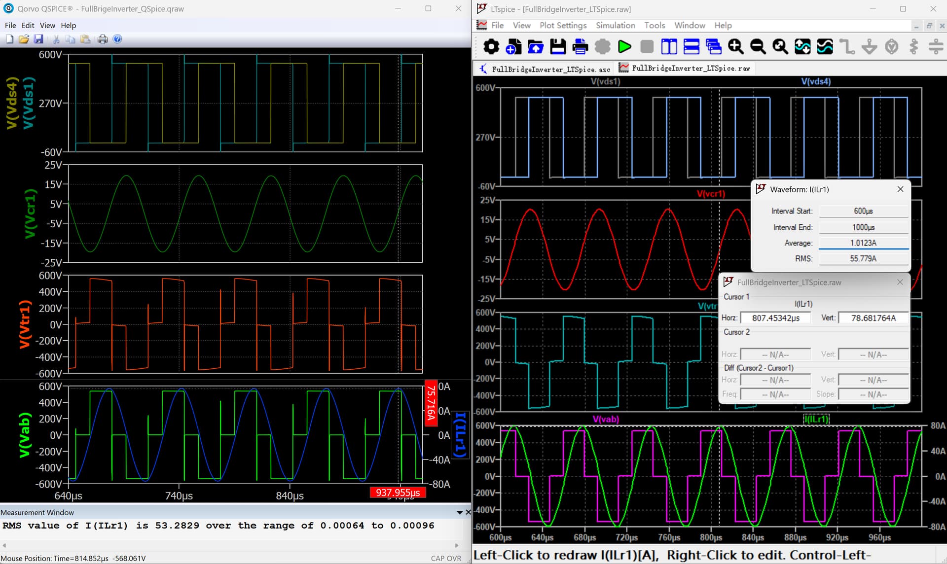
I am a new user and can only upload one image at a time, so waveform image see below.
Why do the waveforms differ in the same circuit?
The effective current value calculated for ILr1 has a difference of 2.5A, and ILr1 maximum value also a difference of 3A.
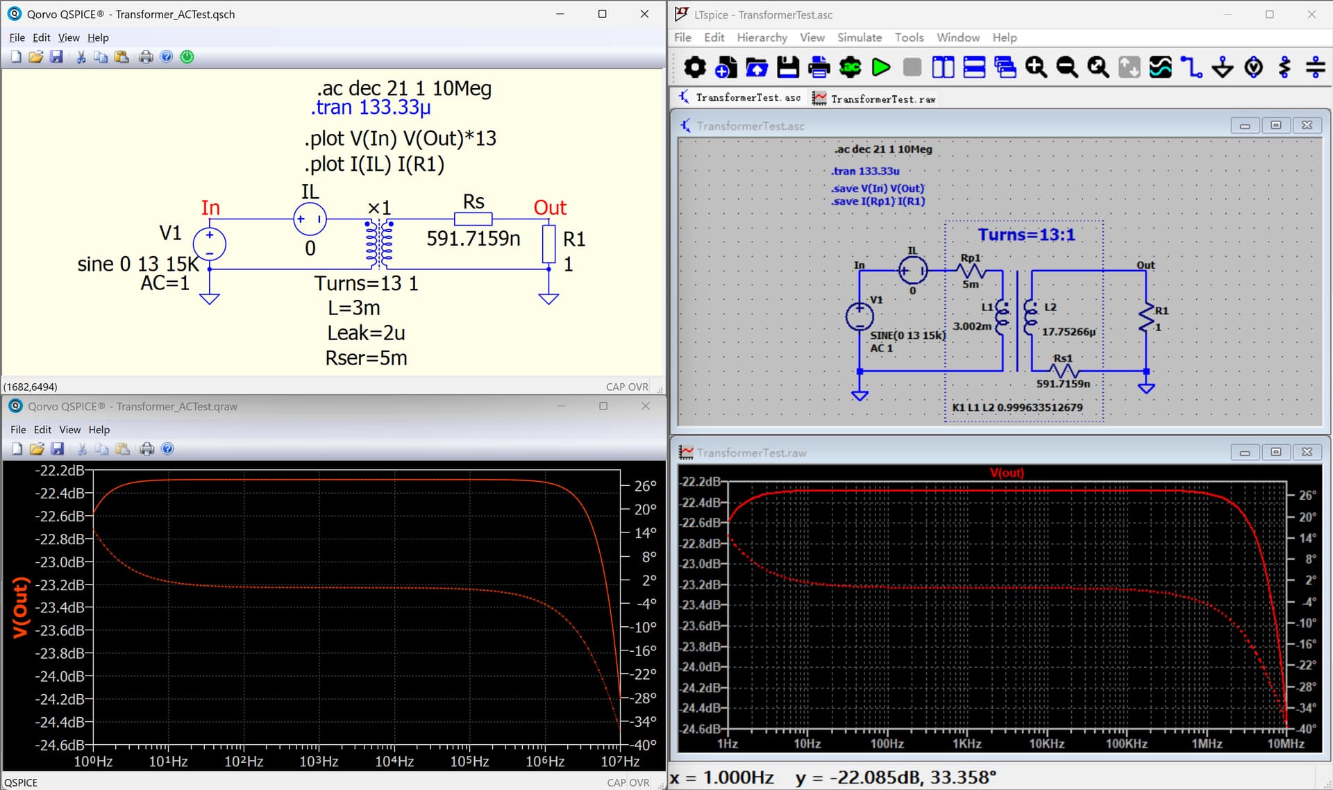
Additionally, I tested the transformer in both QSpice and LTspice, and the results were the same, it’s waveform image see below also.
Simulation is a numerical process, and tolerance is expected. There are many .option parameters that affect accuracy and simulation speed. For a fair comparison, both simulations should run from the same netlist, with options set up as closely as possible.
If anyone wants to compare SPICE simulations, they have to be very familiar with the differences in SPICE programs. Qspice and LTspice have different timestep schemes, default parasitic settings for inductors (Qspice with Rpar=INDUCTANCE÷(15.91×GMIN) and LTspice with Rser=1mohms), and different Rser/Rpar arrangements for capacitors, etc… There are devices within SPICE that can behave differently, so it’s advisable not to delve too deeply into comparisons.
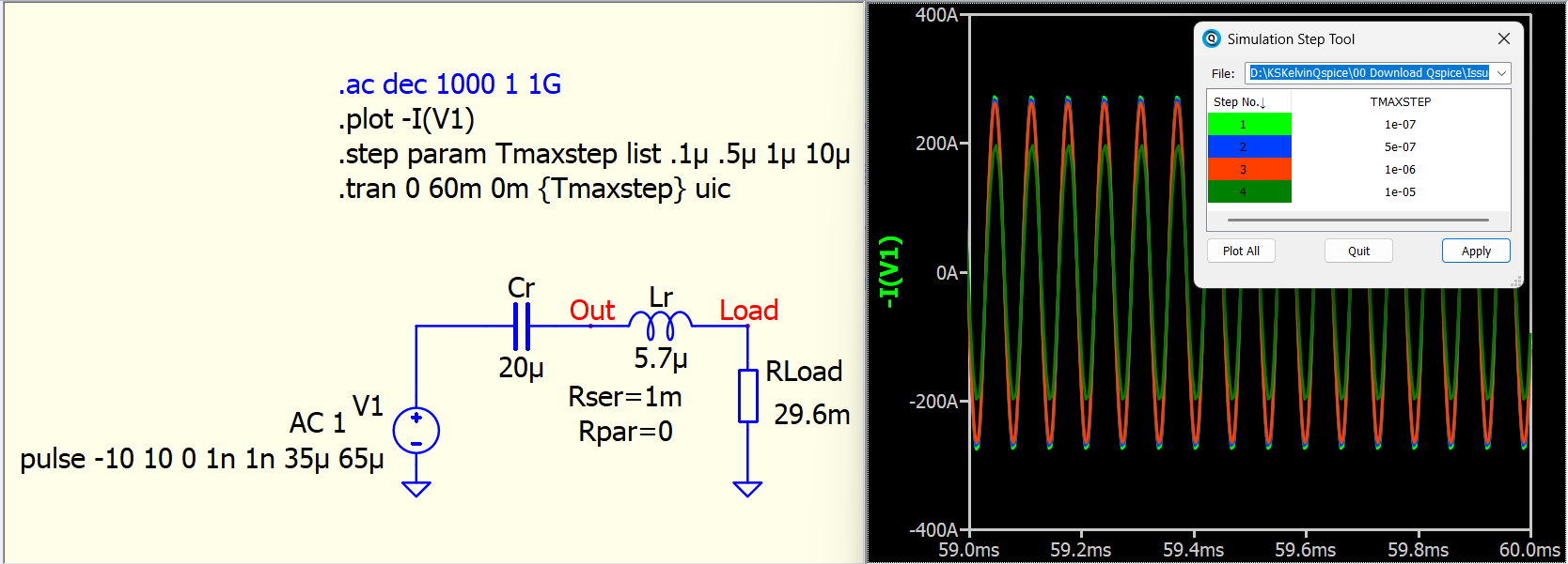
For a switching circuit, my suggestion is that you set the maxstep to at least 100 times smaller than the pulse period if you are seeking more precise results.
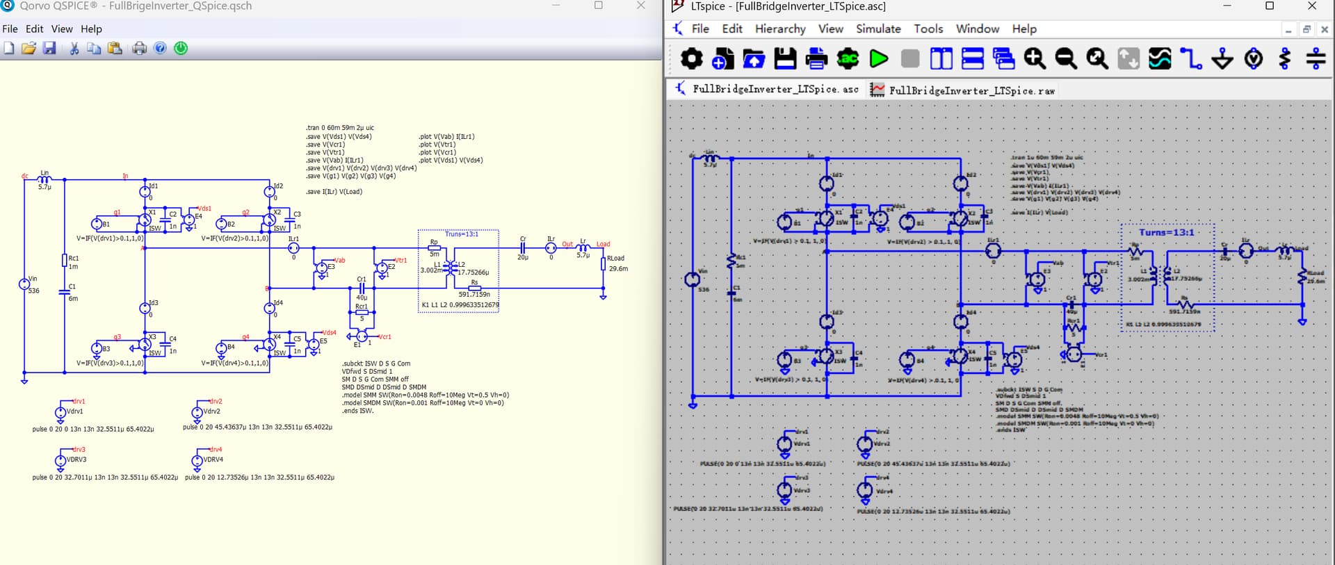
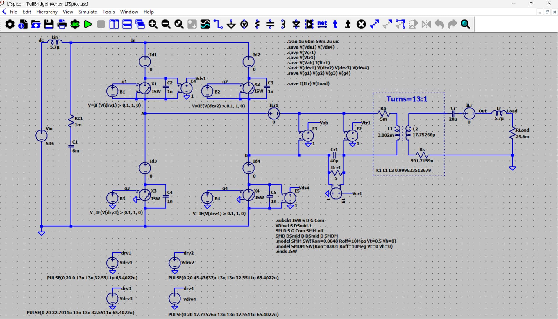
[1] I modified this Qspice schematic by renaming the voltage source used for current sensing to begin with V instead of I. This modification allows the netlist to run directly in LTspice.
[2] The timestep has been reduced to 0.1us for a more precise timestep scheme.
[3] Another important adjustment is in LTspice: go to Tools > Settings > Hacks > Enable: always default inductors to Rser=0. Unlike LTspice, Qspice set Rser=0 by default.
Thank you for your help.
I’m not here to deeply compare QSpice and LTSpice, but I recently switched from LTSpice to QSpice and encountered a situation in QSpice with a circuit I had previously used from LTSpice that I couldn’t understand.
Additionally, I find that for this circuit, just by limiting the timestep to about 100 times smaller than the pulse period, the simulation results were already very close; but considering parasitic parameters could make the results even closer.
Once again, thank you for clearing up my confusion, thank you!
I delved a little deeper into your circuit. Even in LTspice, if you set the maxstep to 10us, it will yield a current peak of about 70A.
I simplified your circuit to only include the output resonant load: Lr, Cr, and Rload. If the maxstep is set to 10u, it will result in a significant error, and in Qspice, this error is reduced with smaller and smaller maxstep.
This resonant circuit has a very high Q, which is why timestep is essential. I suspect LTspice takes a smaller timestep compared to Qspice when handling this resonant network, even though both have the same recommended maxstep. Nonetheless, this is an interesting case as I hadn’t considered that the error in this switching circuit is actually related to the load condition.
If you commonly work with high Q networks, be cautious about the maxstep, regardless of which spice platform you are using.