Based on the QPA2237 chip, we have built a transmitter with a power of 10W, covering a frequency range from 30M to 2500M. During the testing, we found that under static conditions (without input) or with a small power input, the problem of the chip would keep increasing and would exceed 150 degrees Celsius. We adopted the backside of the chip specially designed for heat dissipation, and used heat sinks for cooling. May I ask, for the QPA2237 chip, is there anything that needs to be particularly noted when it comes to heat dissipation?
Below are the pictures of our board cards and the scenarios of heat dissipation. We would like to know at what temperature QPA2237 can operate safely.
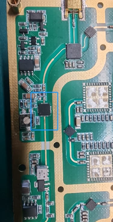
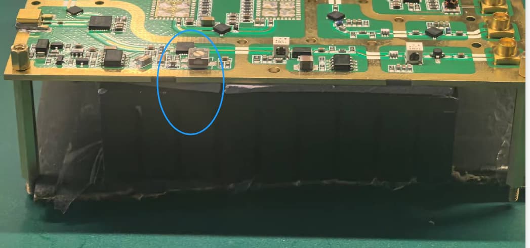
The QPA2237 could be dissipating 10Watts even under small signal conditions with the nominal bias of 32V/360mA. That’s a lot of heat to get out of the device. The Qorvo eval board uses an array of vias under the MMIC to take the heat out of the device, and the PCB thickness is just 8mil. The thin PCB helps to minimize it’s thermal resistance. It looks like your PCB is much thicker, and hence thermal resistance of PCB will be much higher. The QPA2237 is going to overheat on your board. You could either use a much thinner PCB, or keep the PCB thickness and use an embedded copper coin in the PCB under the QPA2237. You also need to use a heatsink, and ensure a good thermal interface between the PCB underside and the heatsink. For the thermal interface you could use epoxy preform or thermal grease.