Hello,
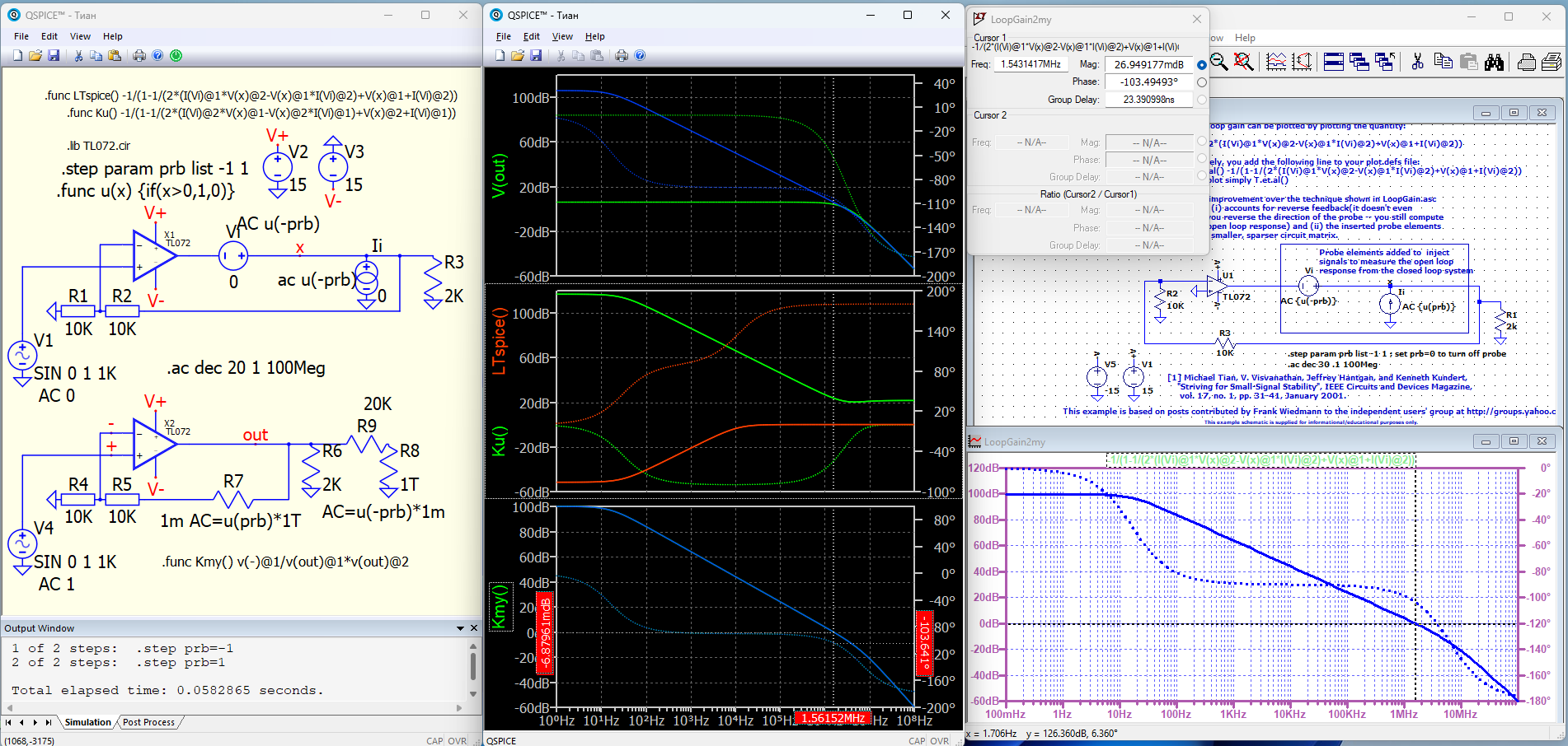
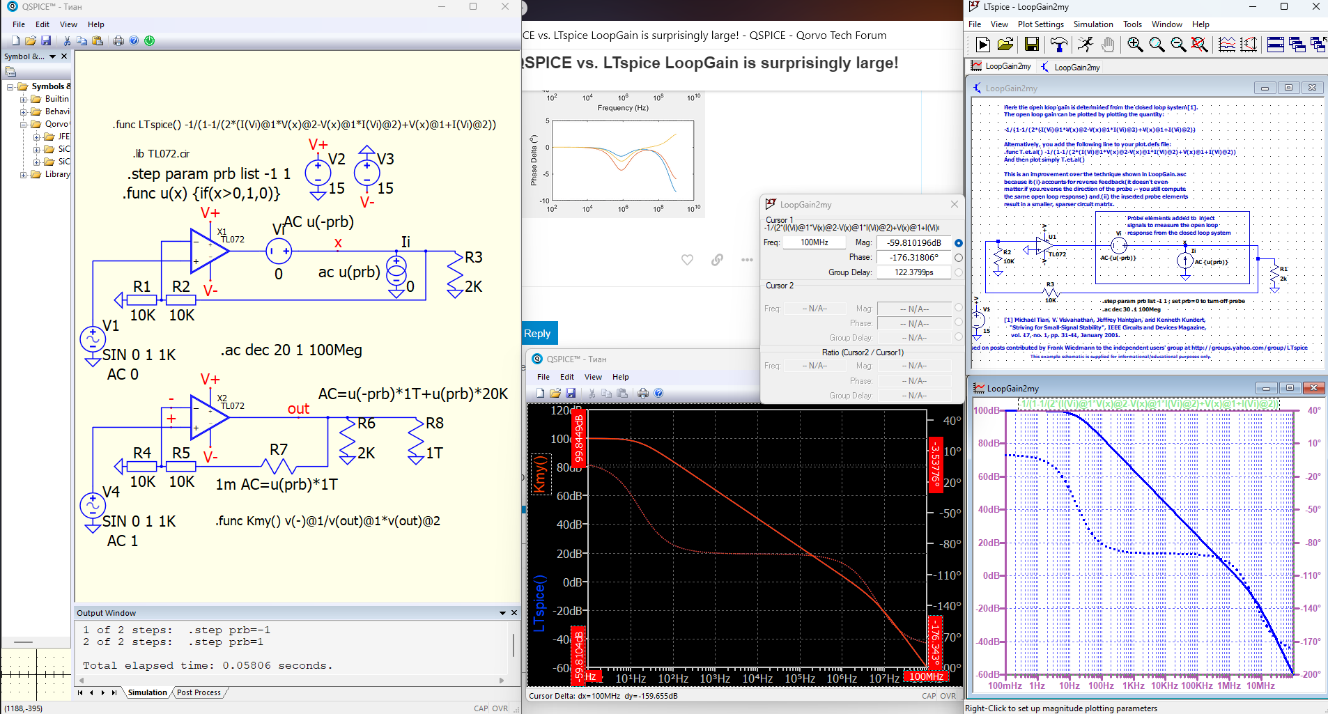
I tried simulating the loop gain of several negative feedback circuits using QSPICE, but I was confused because there was a surprisingly large difference compared to LTspice, which I had been using regularly. I don’t know the reason as I don’t know any calculation algorithms for both.
As a typical example,
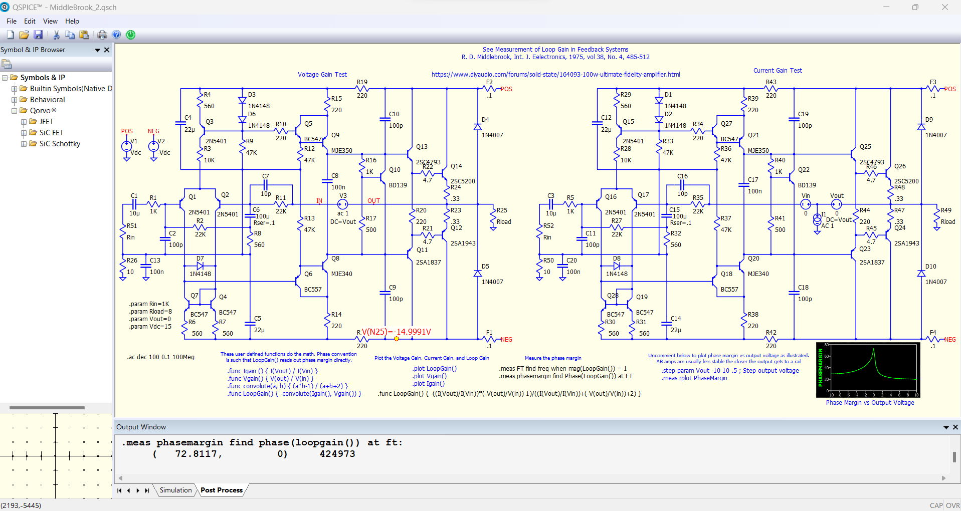
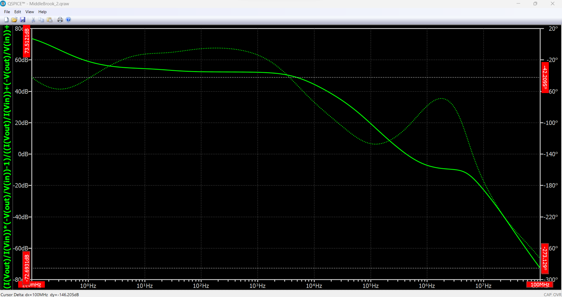
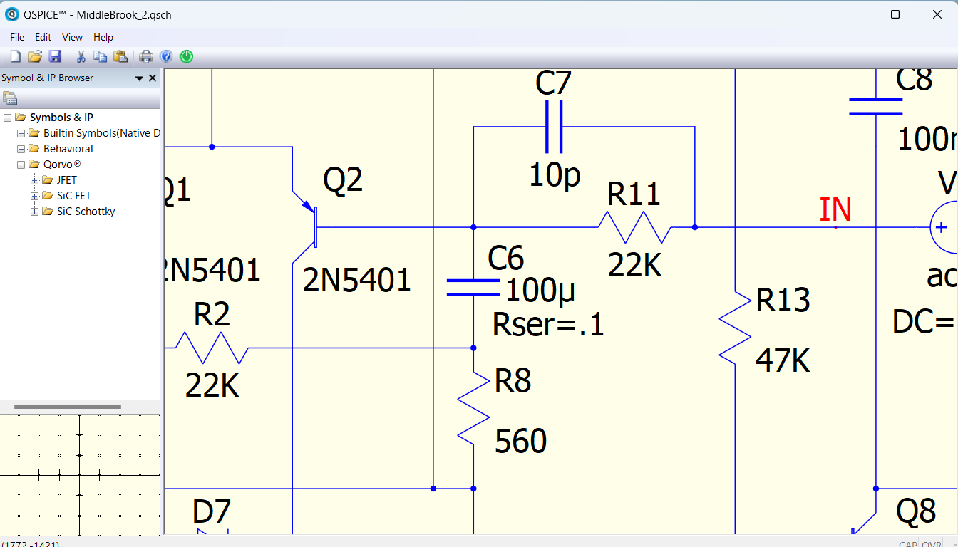
I used Middlebrook.qsch, one of the QSPICE DEMOs, to compare the frequency characteristics of LoopGain by porting the exact same device model as QSPICE to LTspice.
The formula for Middlebrook’s loop gain is:
Both QSPICE and LTspice
Hi,
I think those who have tried QSPICE from LTspice have seen similar differences regarding LoopGain.
However, this is an untouchable area that only developers can solve. Therefore, I look forward to hearing Mike’s views.
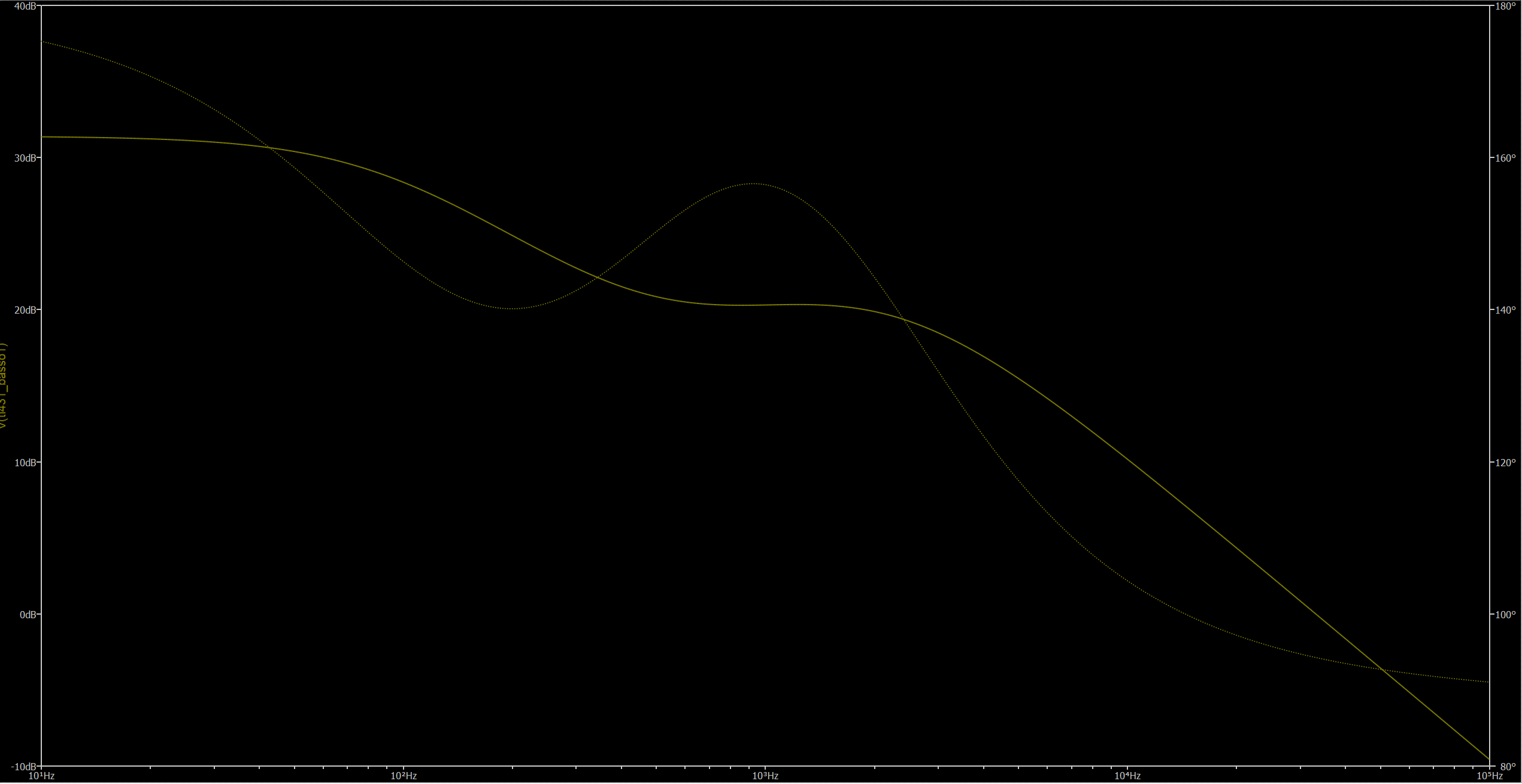
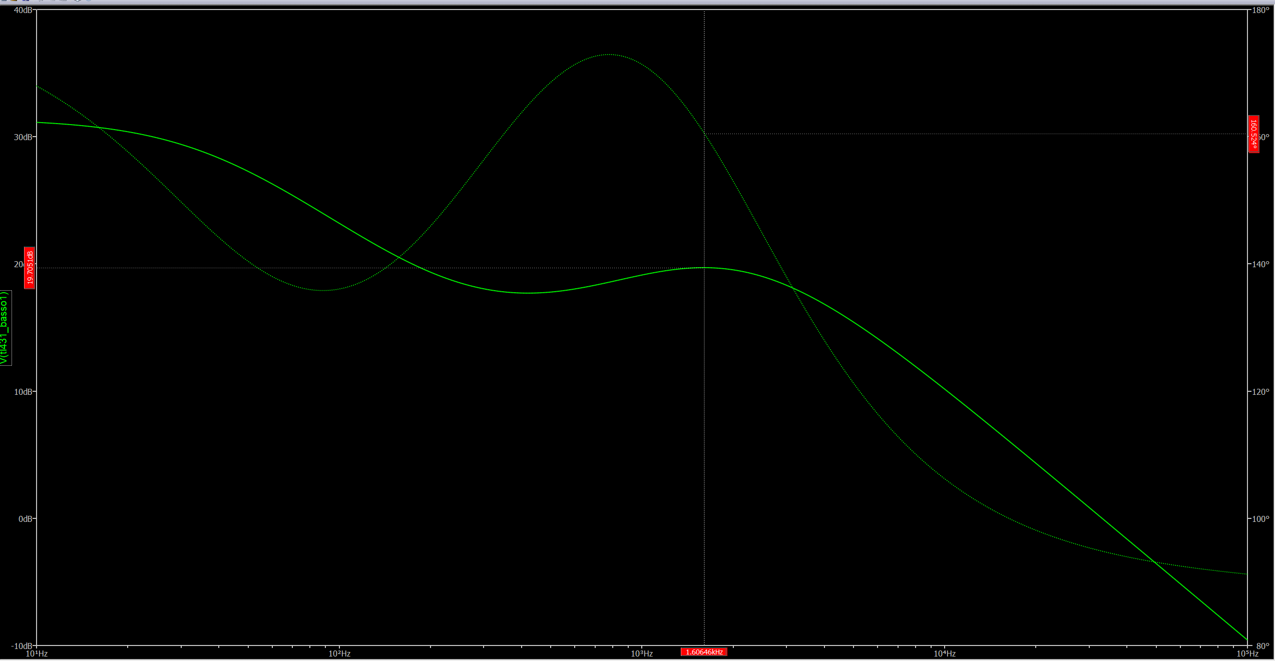
I found the Issue in my circuit, so the difference is neglicatble between the two simulators, but my circuit is much less complex than yours.
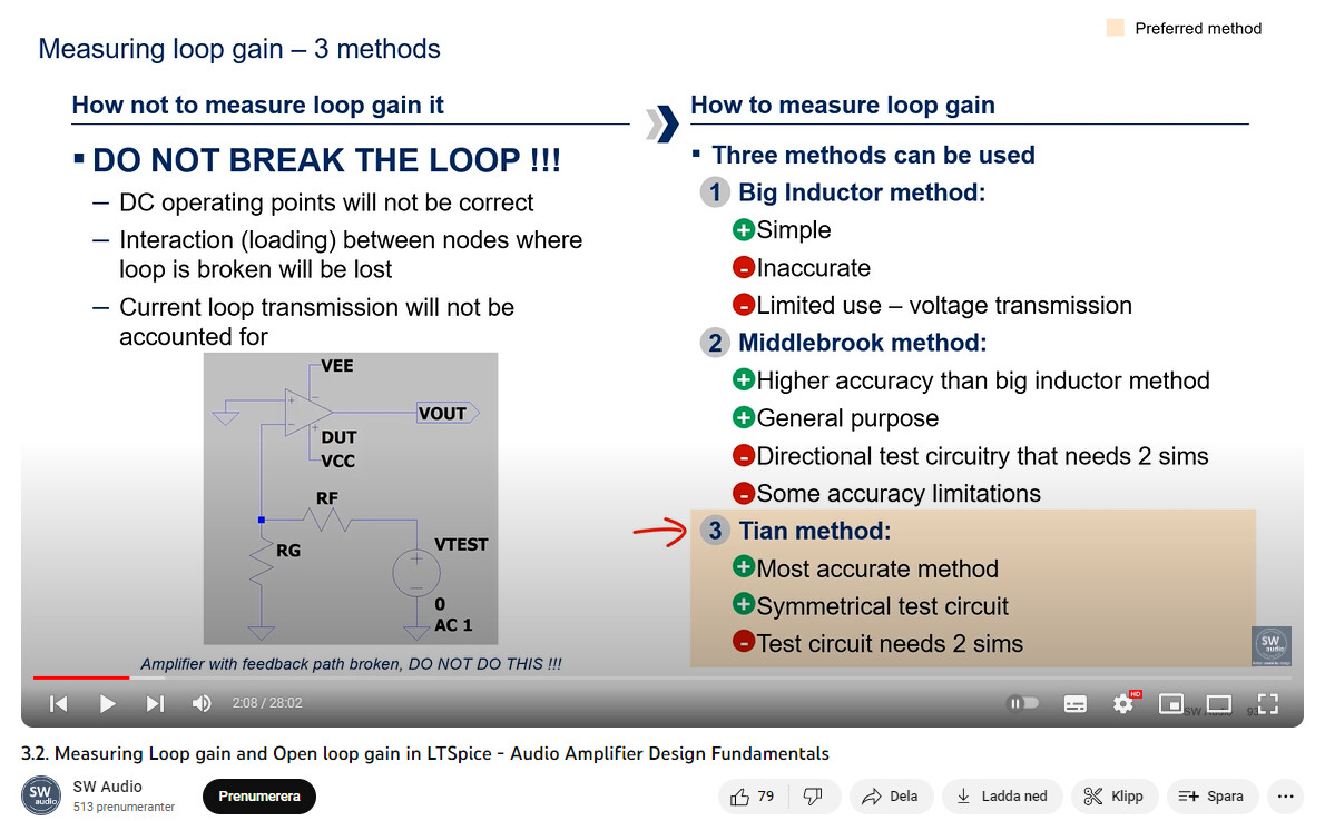
Anyway have you tried the Tian method in both LTspice and Qspice?
In my knowledge it’s more accurate, and less prone to error in the calculation and more immune for the polarity of pertubation.
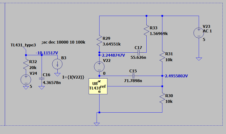
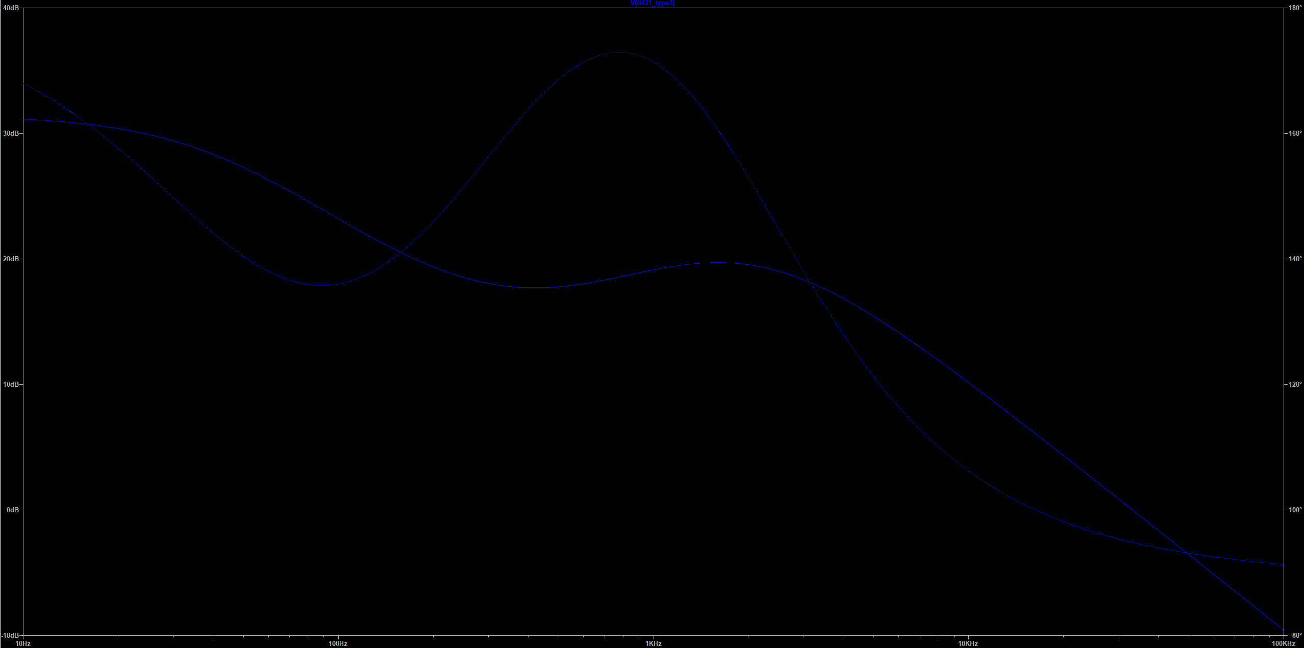
I have a similar problem.
Took the schematic from the LTspice Education folder. Entered the same circuit in Qspice, and got a completely different result. I replaced the operational amplifier in the original circuit with a simple model and changed some nominal values.
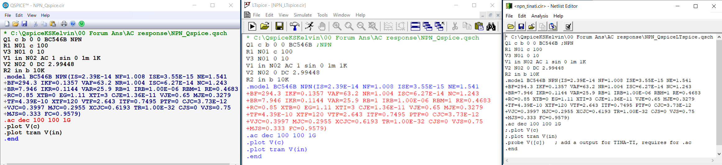
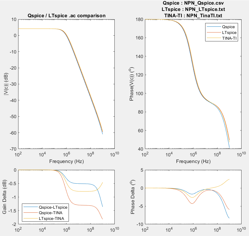
A npn transistor model is used to compare Qspice, LTspice and TINA-TI .ac analysis.
The circuit is built in Qspice, export to Netlist, and run netlist in LTspice and TINA-TI (slightly modification is required, but none are related to device parameters)
Test circuit with npn transistor, use BC546B model which is from LTspice library.
All data are exported and compare in this chart, simulation uses their default options.
All simulators give slightly different results. If only one transistor can have deviation between simulators, deviation can be expected for a circuit with multiple nonlinear elements (diodes, transistors)
Different method, formula, implementation, numerical method and options between simulators, it is common that results can deviate.
I found an Issue within LTspice for the model used,
apparently LTspice round every Emission coefficient for diodes nowadays to 0.1 if it’s lower.
So when I changed the Emission coefficient for the diode to 0.1 in the subckt affected by this rounding they give the same results. Now the simulations coincides.