The CIRs received by the two antennas(STS0 CIR and STS1 CIR) are significantly different

Hi, everyone!

I’m conducting a research project about single-anchor AOA/PDOA Localization. I am trying to obtain AOA/PDOA from two CIRs received at the anchor side instead of that reported from the device. But I’ve gotten caught with some problems.

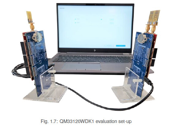
I’m using QM33120 WDK1. The system includes one Non-AOA tag with single RF port and AOA anchor with two RF ports.

I set the tag with single RF port be in Simple Tx with PDOA mode and set the anchor with two RF ports be in modified Simple Rx with CIR reading mode(Enable the PDOA_Mode_3). Therefore, both the two boards enabled the PDOA Mode to enable the mearment of PDOA.

In this way, I can extract the Ipatov CIR, STS0 CIR and STS1 CIR.
Take one case as an example,


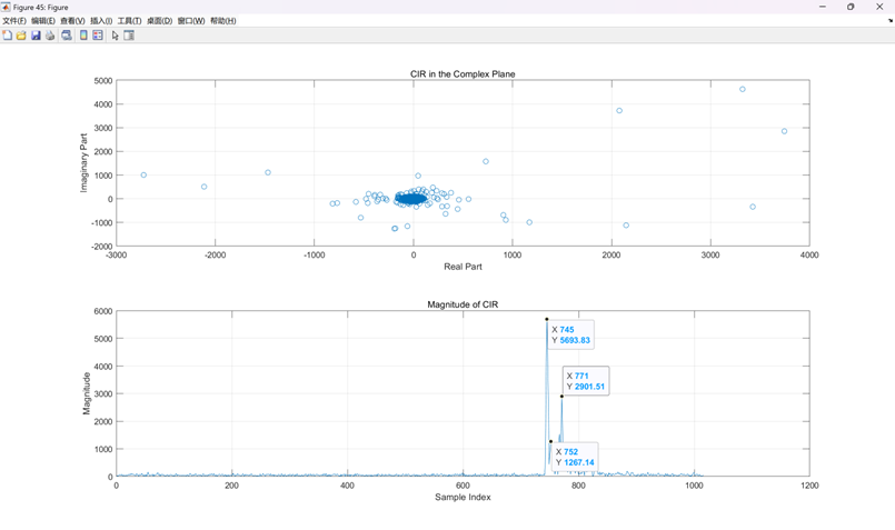
And this case is correct.

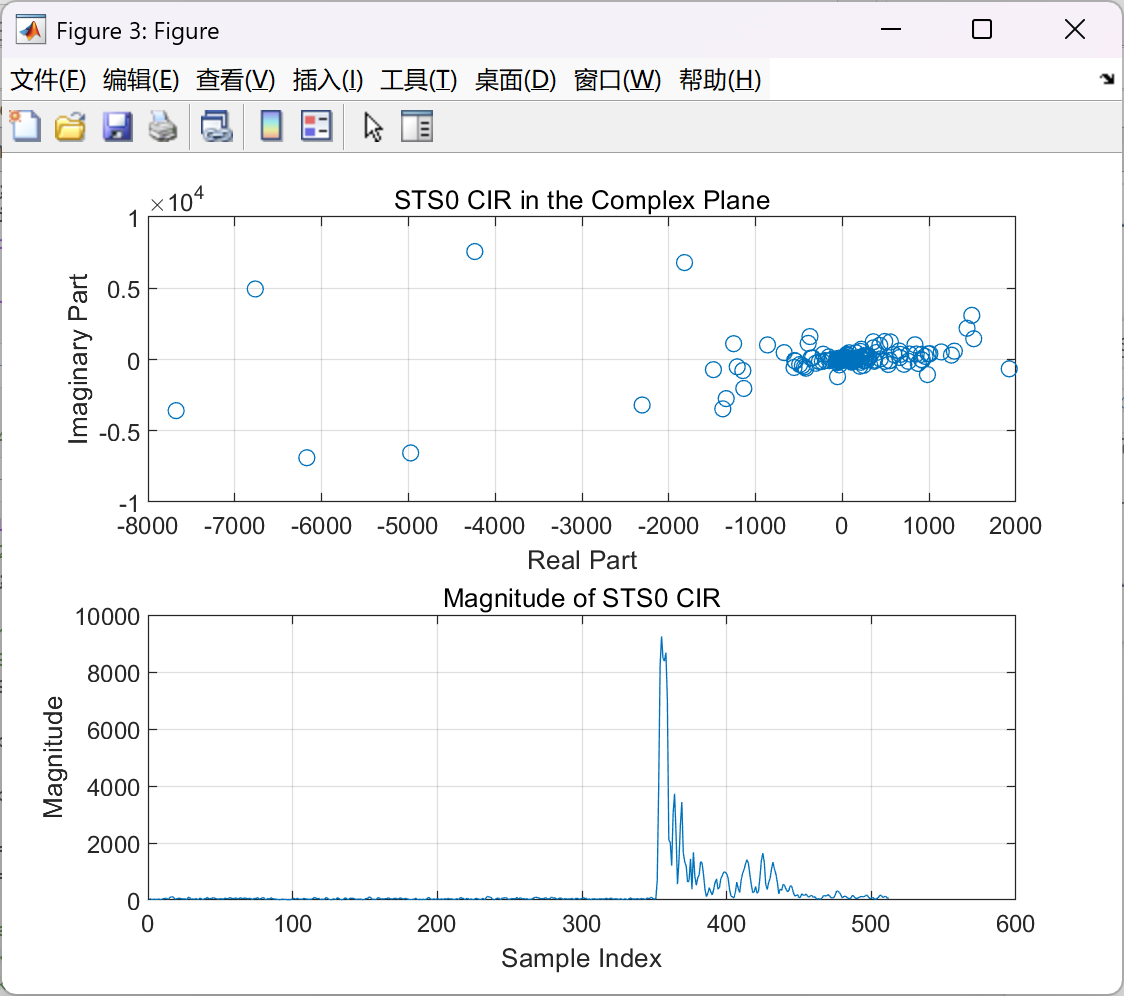
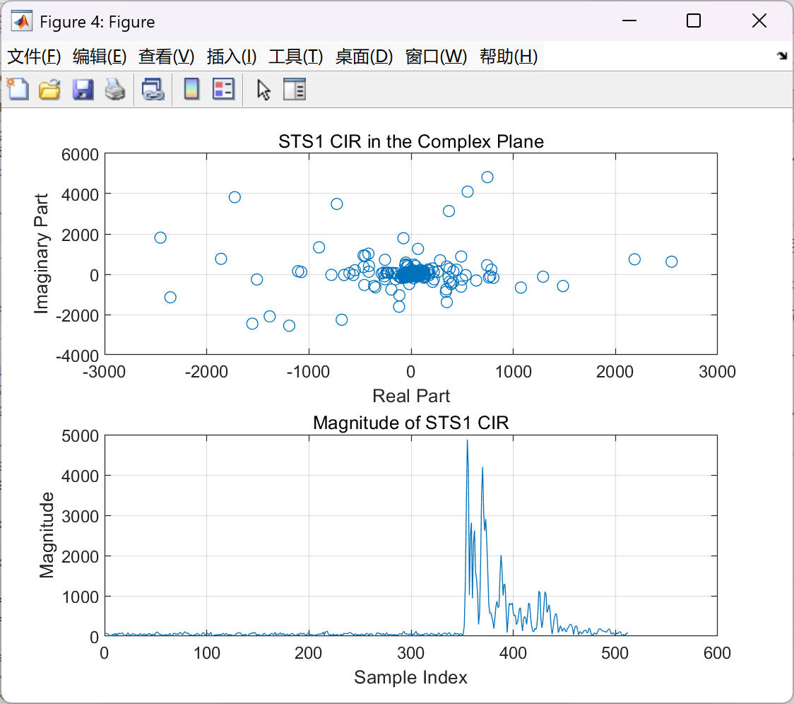
1.However, there are some cases whose CIRs are not normal.
The CIRs received by the two antennas are significantly different
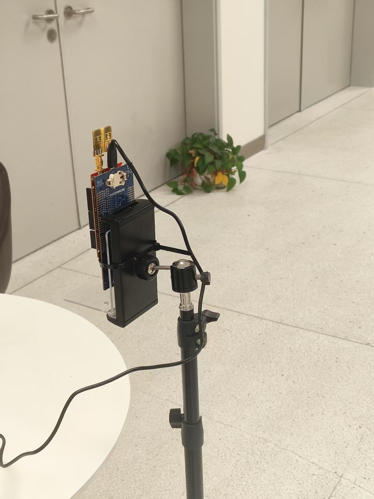
However, there are some cases. For example, when the tag is placed at 30 degrees to the left of the anchor’s normal direction, the received CIRs from STS0 and STS1 show a significant difference as the following figures show:


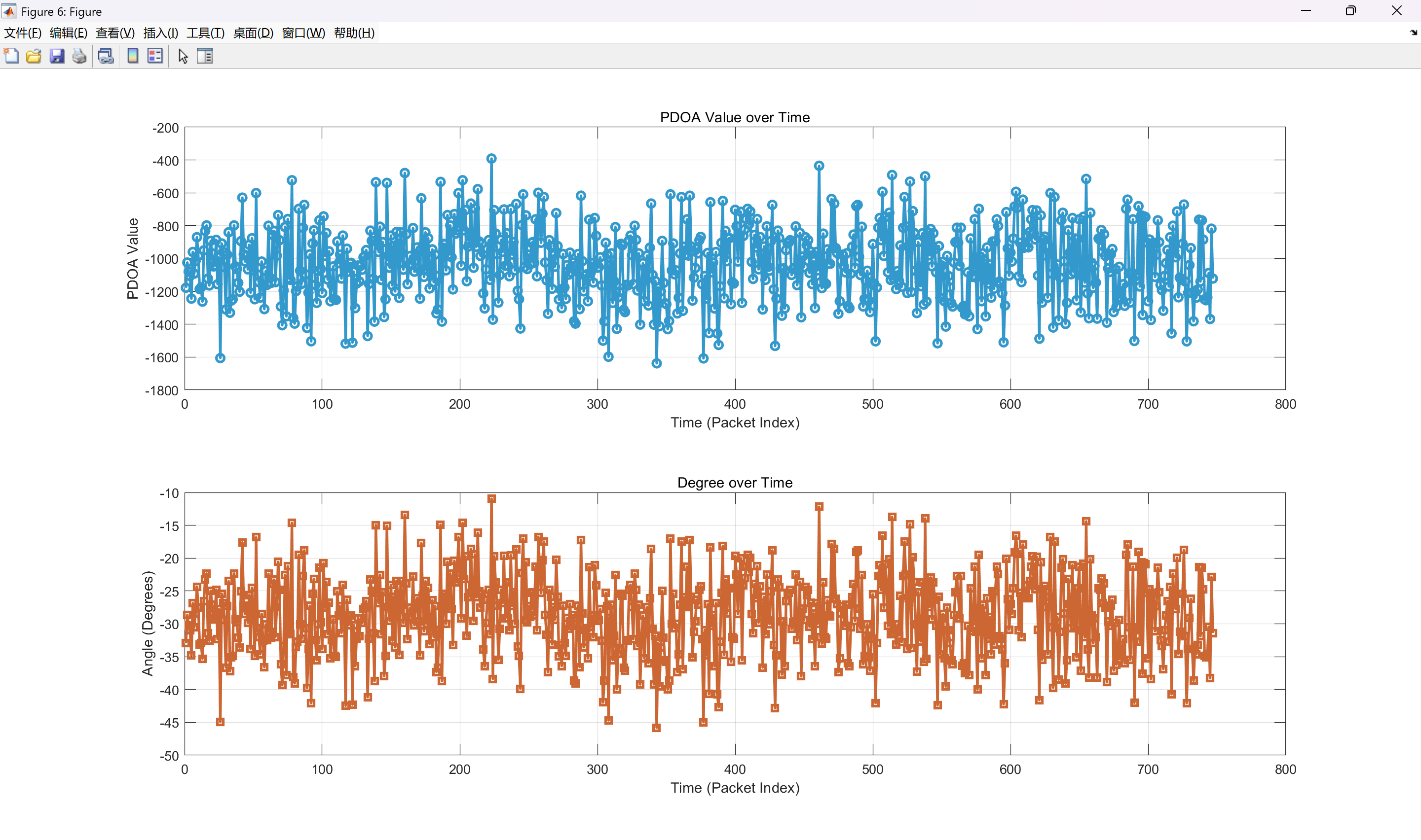
2.Besides, the PDOA and AOA I extracted from CIRs are incorrect with the ground truth even if I calibrated them.
I attempted to estimate the AOA by extracting the phase difference of arrival (PDOA) from the direct path peaks of the CIRs. However, even after applying calibration, the results remain inaccurate, as shown in the figure below:

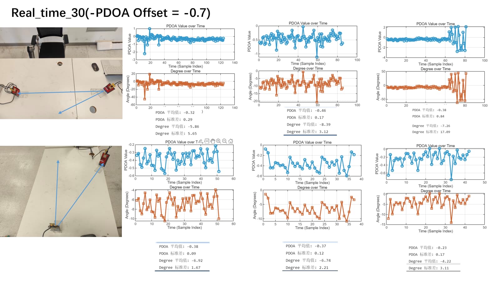
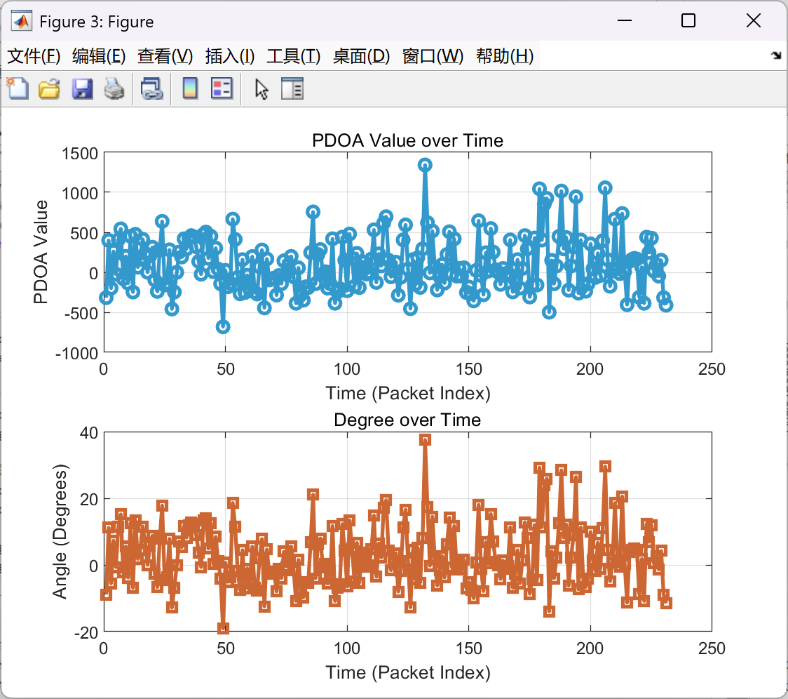
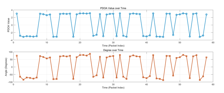
3.Finally, the PDOA and AOA I extracted from CIRs are unstable (I find that most cases are due to the two different CIRs)
Sometimes, abrupt phase shifts occur (e.g., jumping from 2.xx to -2.xx), which leads to significant drift in the results, as illustrated in the figure below:

Could you kindly give me some advice about these problems?

It’ll be much appreciated if you could reply to me ASAP.

Thank you all !!!

I would appreciate it if someone could help me analyze the reasons. Are there any issues I may have missed?

Hello,

Something you can do is to compare your results with the ones computed by the chip. So that it may help you to understand where is the issue. Another thing is to plot a graph with real angle of arrival in x axis vs measured PDOA in y axis. If your board is well calibrated you should get a correct curve from -60 degrees to 60 degrees.

Thank you for your prompt response!

However, I think the issue lies in the inconsistency between the two CIRs. I obtain the AOA/PDOA estimation from the peaks corresponding to the first path of each CIR.
If the two CIRs (STS0 CIR and STS1 CIR) are different, how can I achieve accurate PDOA estimation?

Could you please help me understand why there is a discrepancy between the two CIRs, and why their signal strengths differ significantly?

In fact, the results computed by the chip seem to be not accurate as well and it’s very unstable.

And I’ve tested 30°,60°,-30°,-60° these four angles. I compared them with the ground truths. The result was not ideal.

By the way, how do you define the “well calibrated” ? Directly subtract the PDOA value when the tag is placed at 0 degree?

Hi @Sending ,

A good starting point to debug your issue would be to perform the PDoA/AoA with QM33120W kit that you have by using QM33 SDK 1.0.2. Keep in mind that the PDoA antenna in that kit is optimised for Ch9 operation. If you’re using Ch5, then you need a different PDoA to AoA LUT.

Kind regards,
Emre

OK. I’ll try it!

Thanks for your advice.

Hi, I got caught with a problem.
When I ran the simple_rx_PDOA example, the program was stuck at the line of code: while (!dwt_checkidlerc()) /* Need to make sure DW IC is in IDLE_RC before proceeding */ { };

Could I just comment out this line of code? If I don’t comment out, how should I modify the code to run it?

I modified the code and used SPI1 to communicate with the chip instead of SPI 2 to figure out the hardfault.
And then I ran the simple_rx_pdoa example to perform PDOA/AOA.

The results are shown in the following figure:

The tag was placed at 0 degree to the anchor. However, the measured PDOA/AOA was neither accurate nor stable。

Make sure the devices facing each other as shown in the quick start guide.


In the picture of your setup, it looks like the boards are turned 180°. The antenna on the anchor is directional, PDoA won’t work at the back of the antenna.

Oh, my god! You got it!
Thanks for pointing out the problem.
I’m so excited to realize this point and I can’t wait to have a try!

Yes, I’ve conducted some experiments.

The results show that the adjustment had a significant positive effect.

The average AOA was close to 0 degrees when the tag was placed directly in front of the anchor (at 0 degrees).
However, the standard deviation of the AOA was around 9 degrees, indicating that the measurement was still not very stable.

And there was another question. When I flip the anchor board over, the micro-USB cable blocks the two receiving antennas.

This could potentially affect the signals received by the antennas, thereby impacting the accuracy of AOA measurements. Additionally, I can only use the J2 port on the top side of the board, and I am unable to use the J3 micro-USB port on the left side for RTT communication. In fact, using the J3 port doesn’t even provide power to the board.

Under these circumstances, how should I communicate with my anchor?

Oh, I find that I can adjust the orientation of the antennas.

The problem has been fixed!