Hello
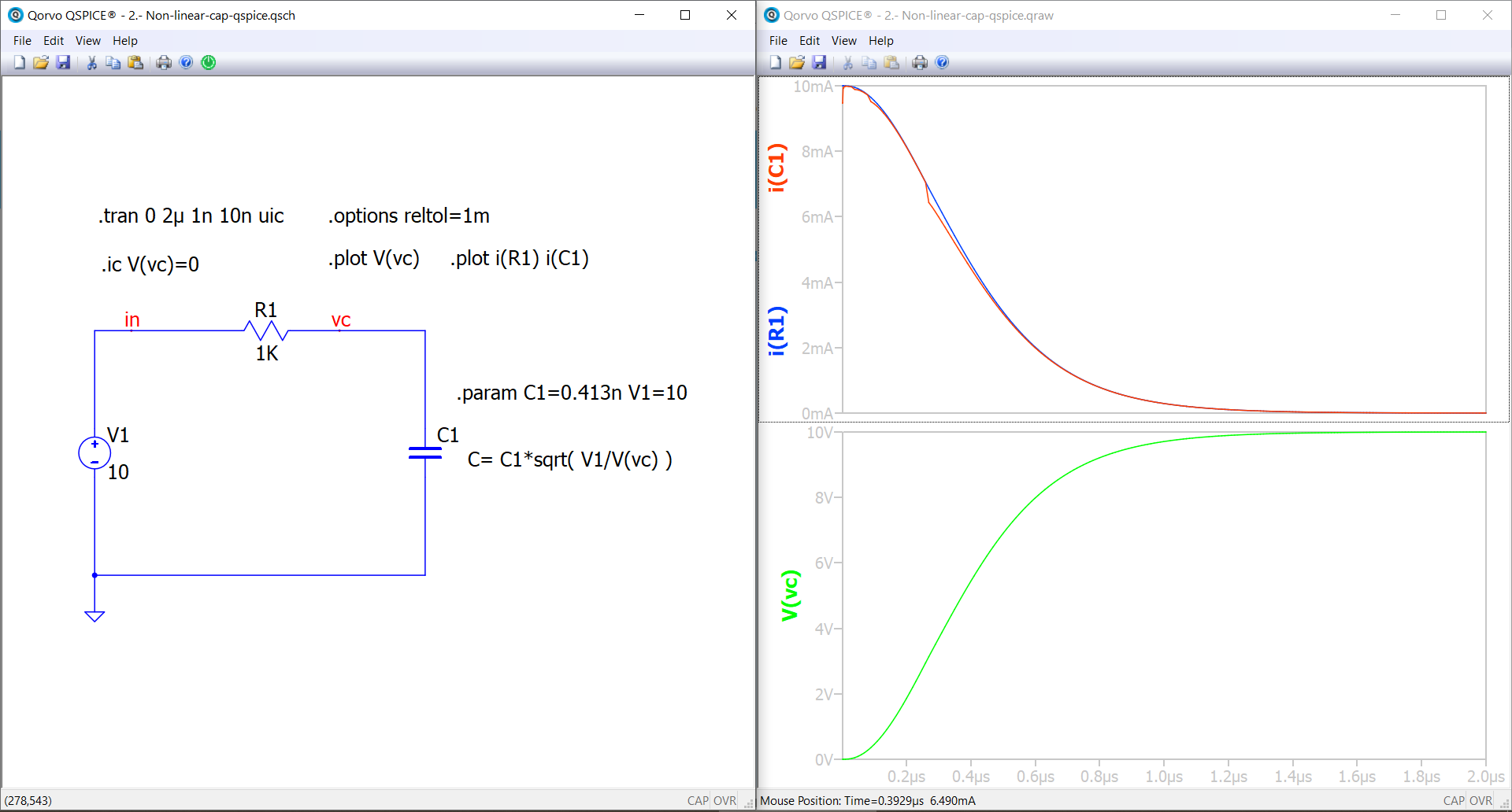
I am testing Qspice non-linear capacitors. Please, see attached circuit.
When the initial voltage of the cap is 0, it seems to work well, even though there is a strange difference when measuring the current through the resistor and through the cap (?).
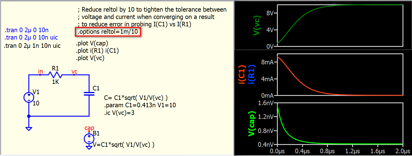
However, when the initial voltage of the cap is set to another value, for example 3 V, the results seem to be wrong. The capacitor voltage starts from 3V at the very beginning but drops very quickly to another value. Any idea on what could be the issue?
Thanks!
The problem you encountered, I am no expert but just to share what I observe or know (could be wrong)
Difference between current through the resistor and capacitor
Sometime, you can see difference in current for devices connected in series in SPICE simulation. SPICE uses Modified Nodal Analysis (MNA) to solve the circuit. My understanding is that, SPICE arranges circuit into a matrix with conductance * voltage = current (i.e. [G][V]=[I]) and use Newton-Raphson Method to solve for the voltage. Then it verify if sum of current into a node is within certain tolerance (reltol, abstol) as one of the convergence criteria.
Capacitor voltage drops at the very beginning @alastas is correct, it is related to UIC. Be very careful about UIC!
For a .tran simulation, the underlying sequence involves initially performing a .op operation, and then starting .tran simulation from first timestep with t=0s based on the .op result.
UIC, which stands for Use Initial Conditions, essentially means skipping the .op operation and commencing the simulation from an “incorrect initial condition.” This is the term Mike might use if asked about why using UIC yields unexpected results. If you refer to the LTspice Help, it emphasizes that UIC is not a recommended option. People often misuse it and subsequently complain about its outcomes. UIC is simply a way to attempt an incorrect initial condition to see if the simulation can proceed.
In Qspice, when UIC is employed and your .tran with Tstart at 0s, if you zoom-in the time axis at the very start, you won’t find t=0s but only time starting from the first time step, as UIC actually skips t=0s (skip .op).
In your example, when UIC is utilized, the voltage V(vc) at the first time step is 3V due to the initial condition set by .ic V(vc)=3. However, since the .op operation is skipped, the simulator needs to calculate the capacitor current when the .tran simulation begins (.tran begin from first timestep).
The capacitor C1 starts the simulation with a sudden application of 3V at the first time step! By using the formula I = C dv / dt, with dt being 0s to the first time step and dv being 0V to the initial voltage V(vc), the current I(C1) will surge. If you add .option maxstep=1p, you will observe that I(C1) can surge up to approximately 1000V at this very first step. This surge eventually pulled down capacitor voltage in second time step.
So, the solution now is NOT to use UIC. This enables the calculation of the DC operating point with .op first, ensuring that the capacitor current starts from 0A in this scenario. 2.- Non-linear-cap-qspice (uic).qsch (3.7 KB)
Thanks for the explanation. I was supposing that it was something of that sort but anyhow it would be good to have exactly the same currents for series devices under any circumstance. I don’t know if it can be fixed somehow
Thank you very much for the excellent explanation.
I sadly realize now that after so many years using spice-based simulators I did not yet understand the meaning of the uic option.
I thought that without adding uic spice calculates the initial dc operating point under zero voltage and zero current condition in caps and inductors but when you use initial conditions in caps and inductors you had to add uic so that spice would calculate the initial operating point under the selected initial conditions.
Now I see the difference between the use or not of uic. Thank you very much!
You are not alone; I had this exact same thought a year ago until I had a chance for Mike to correct my understanding.
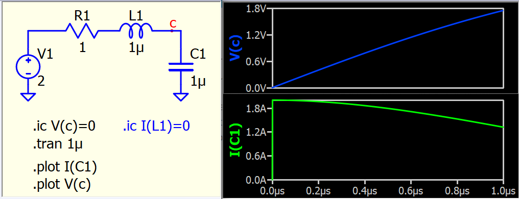
For power electronics circuits, the best way to start a power supply is to define both the initial voltage of the output capacitor and the inductor current.
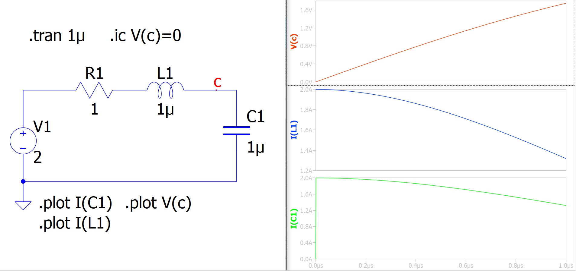
If only V(C) is set to 0V, the .op will give a finite current for I(L1), and the first step will immediately force the capacitor to charge with this current.
Since simulations usually work fine with UIC, most of us never realize the surge in capacitor current at the first step. However, my impression is that some SPICE programs have altered the nature of UIC and somehow actually provide a DC solution when UIC is used, resulting in different behavior among SPICE programs with UIC. In short, I suggest staying away from UIC in Qspice or only using it if necessary.
Thanks for giving more information. This is exactly what happened to me. I never realized about the initial surge.
And to make it worse, the surge is only visible if you plot exactly the current through the capacitor but not visible in the current through the inductor or other elements in the loop.
if you really want to initialze devices, a switch at t=0 is also very good. I’ve seen the good effect on some of my thermal devices to help them initialize at the right temeprature. By the way I never use uic.