SVPWM in codeblock generation

Hi all,

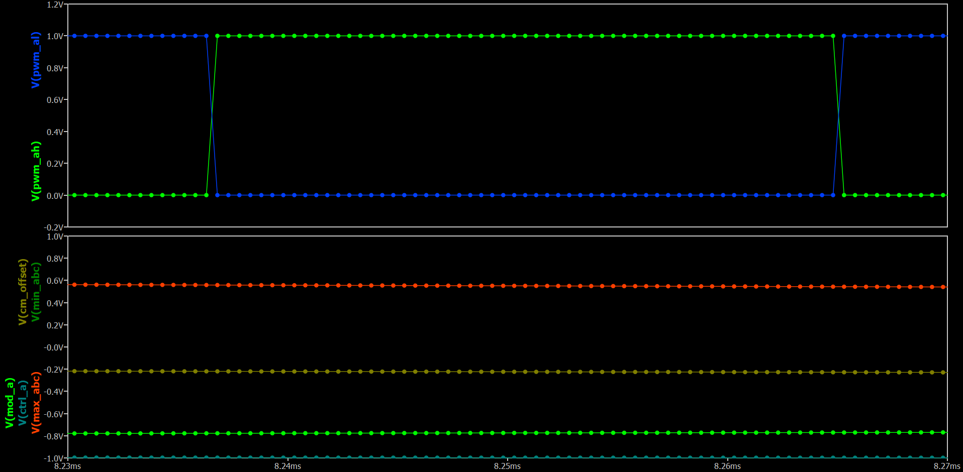
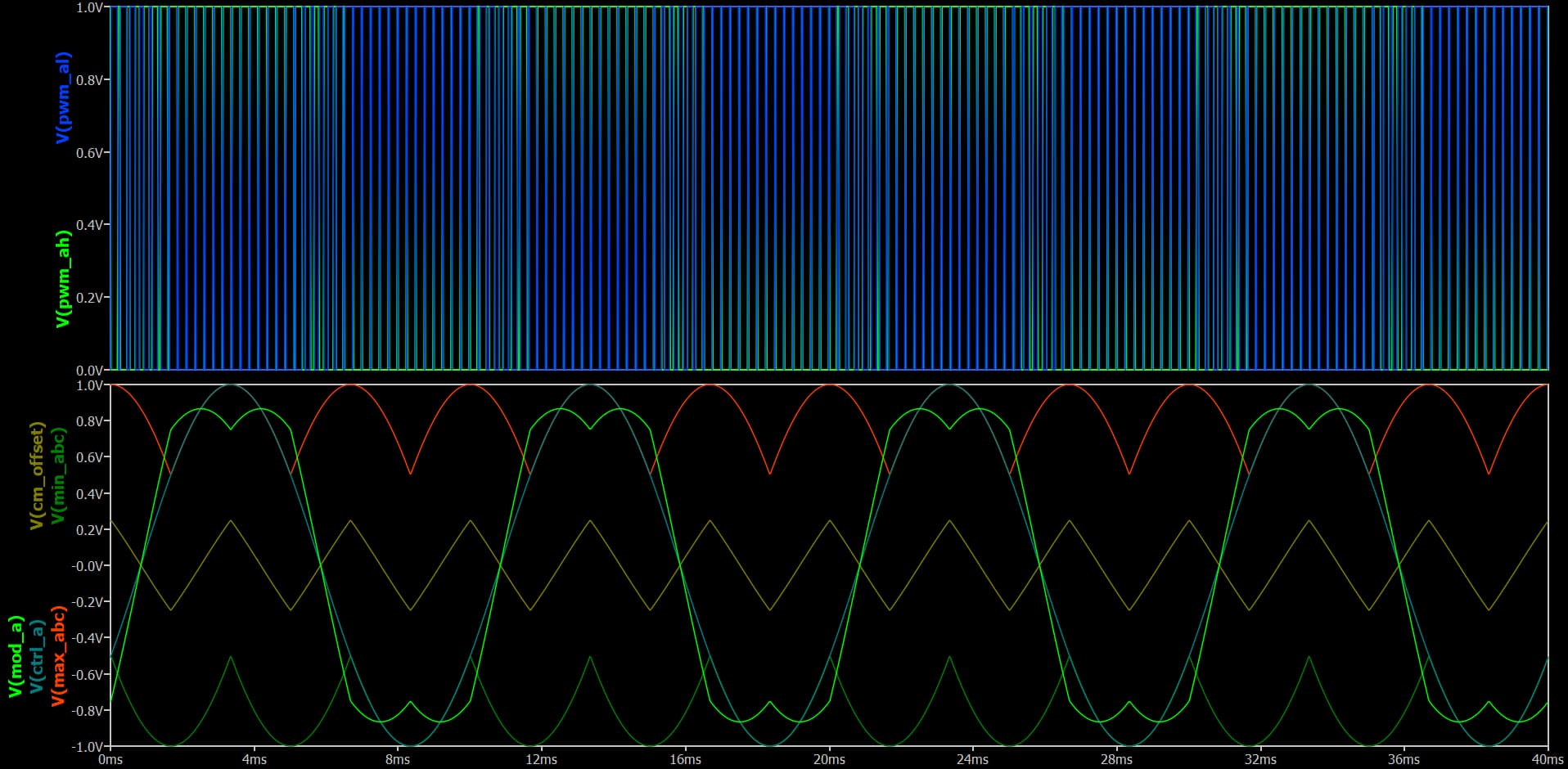
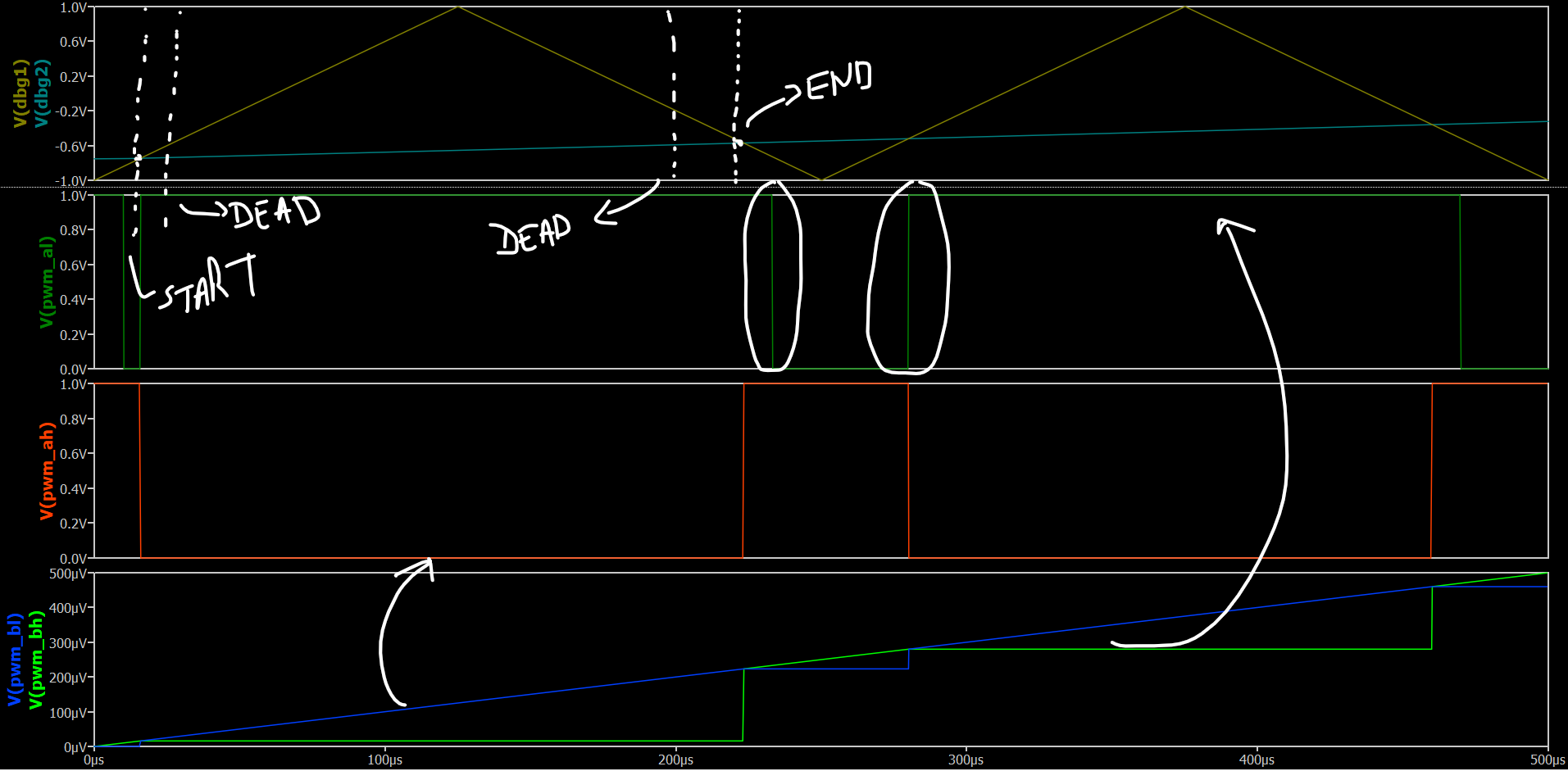
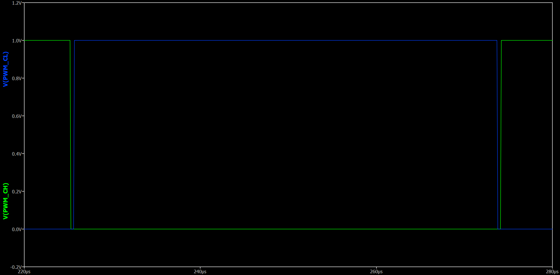
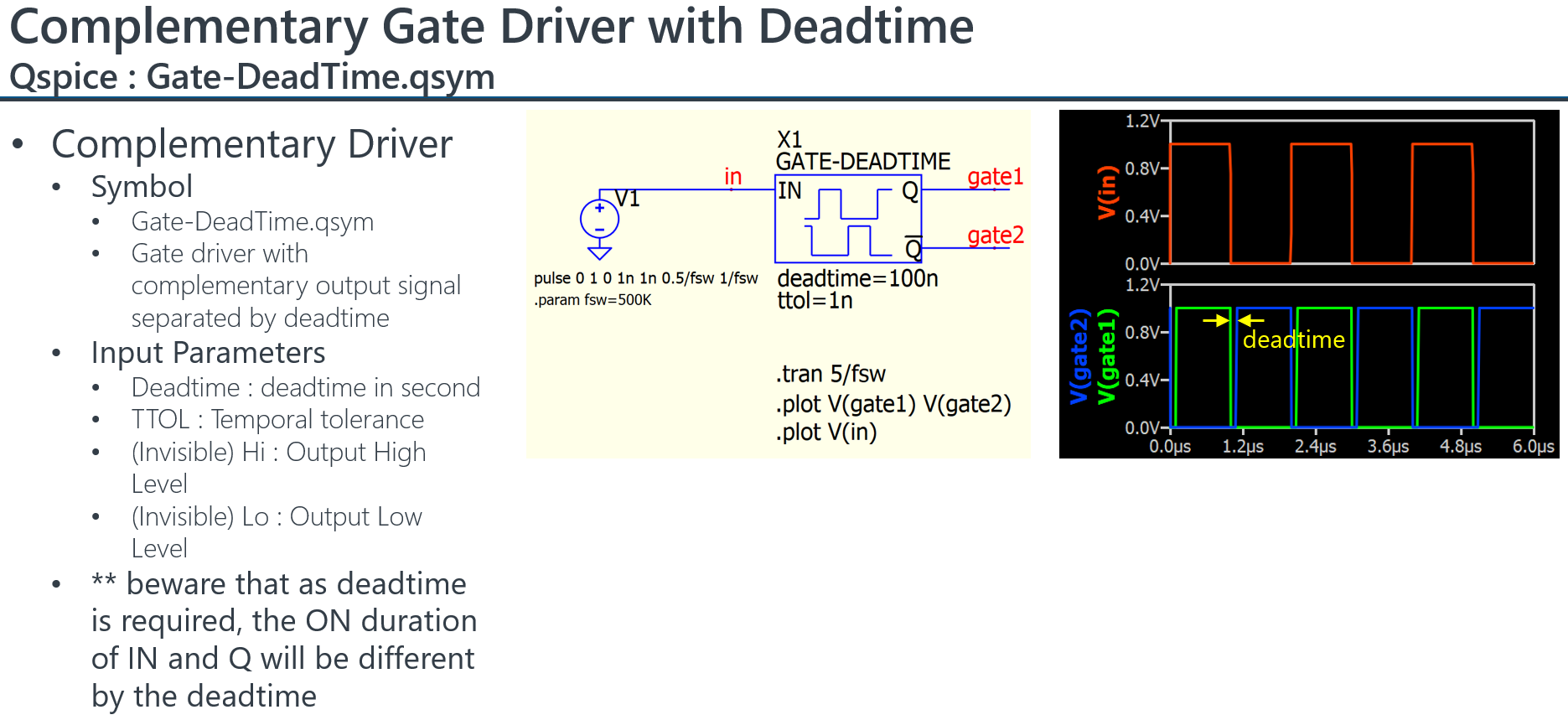
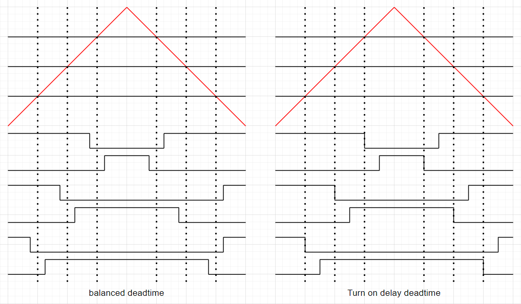
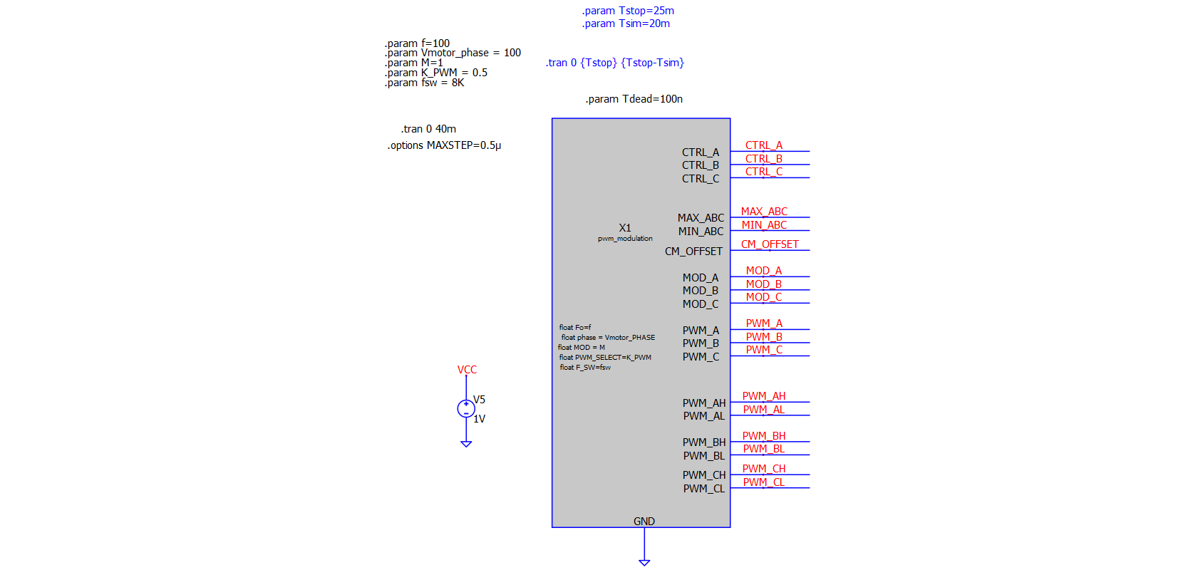
I need some help writing C++ code to generate the PWM timings for a SVPWM modulation technique. I am posting only the PWM generation block. I am struggling to add dead-time to my code; I don’t quite understand how to extract the current time and delay (if that makes sense). I am able to generate this part of the simulation using LOGIC gates to produce the delay, but I would like to do it in code. I have also posted some waveforms to illustrate that the logic behind the modulation signals and the carrier are correct, for anyone that is interested in using this later on.

The final aim is to create a steady-state simulation with an RL load that simulates a motor at a particular operating point. I have achieved this using a more analog approach which is a bit messy.

I can’t attach the simulation as I’m a new member (apparently). I have posted the code below. Once I am able to attach files, I will gladly do so and engage further with anyone that has an interest to produce a more accurate model.

CODE:

// Automatically generated C++ file on Fri Apr 19 22:27:30 2024
//
// To build with Digital Mars C++ Compiler:
//
// dmc -mn -WD pwm_modulation.cpp kernel32.lib

// Library includes - START
#include <stdio.h>
#include <math.h>
#include
#include
// Library includes - END

union uData
{
bool b;
char c;
unsigned char uc;
short s;
unsigned short us;
int i;
unsigned int ui;
float f;
double d;
long long int i64;
unsigned long long int ui64;
char *str;
unsigned char *bytes;
};

// int DllMain() must exist and return 1 for a process to load the .DLL
// See DllMain entry point (Process.h) - Win32 apps | Microsoft Learn for more information.
int __stdcall DllMain(void *module, unsigned int reason, void *reserved) { return 1; }

// #undef pin names lest they collide with names in any header file(s) you might include.
#undef CTRL_A
#undef CTRL_B
#undef CTRL_C
#undef MAX_ABC
#undef MIN_ABC
#undef CM_OFFSET
#undef MOD_A
#undef MOD_B
#undef MOD_C
#undef PWM_A
#undef PWM_B
#undef PWM_C
#undef PWM_AH
#undef PWM_AL
#undef PWM_BH
#undef PWM_BL
#undef PWM_CH
#undef PWM_CL

// Self-defined constants - START
#define pi 3.14159265358979323846
#define freqClk 72000000
#define clkPrescaler 63
#define PWM_MODE 2 // 0= edge-aligned; 1= centre-aligned uni-polar; 2= centre-aligned bi-polar
#define PWM_TYPE 0.5 // 0=DPWM 180; 0.5=SVPWM; 1.0=DPWM 0
#define t_dead 10e-6

#if (PWM_MODE == 0)
int mode = 0; // edge-aligned
#elif (PWM_MODE == 1)
int mode = 1; // centre-aligned uni-polar
#elif (PWM_MODE == 2)
int mode = 2; // centre-aligned bi-polar
#endif

// Self-defined constants - END

// FUNCTIONS - START

double max3(double a, double b,double c)
{
double result=0;

if (a > b && a > c)
{
result=a;
}
else if (b > a && b > c)
{
result=b;
}
else
{
result=c;
}
return result;
}

double min3(double a, double b,double c)
{
double result=0;

if (a < b && a < c)
{
result=a;
}
else if (b < a && b < c)
{
result=b;
}
else
{
result=c;
}
return result;
}

double modePWM(double t, double T) // generater carrier wave
{
if (mode == 0)
{
double Tsw = T;
return t/Tsw - floor(t/Tsw);
}
else if (mode == 1)
{
double Tsw = 2*T;
double Tnorm = fmod(t, Tsw);
double m = 2.0 / Tsw; // slope

  if (Tnorm < Tsw/2) // rising
  {
     return m * Tnorm;
  }
  else // falling
  {
     return 1.0 - m * (Tnorm - Tsw/2);
  }

}
else if (mode == 2)
{
double Tsw = 2*T;
double Tnorm = fmod(t, Tsw);
double m = 2.0 / Tsw;

  if (Tnorm < Tsw / 2)
  {
     return 2 * m * Tnorm - 1.0;
  }
  else
  {
     return 1.0 - 2 * m * (Tnorm - Tsw / 2);
  }

}
return 0;
}

// Define a struct to hold the PWM result - FOR FUTURE USE
struct PWMResult
{
bool pwm_H;
bool pwm_L;
};

PWMResult pwm(double duty, double deadTime, double carrier)
{
PWMResult result;

if ( (1 - duty - deadTime) > carrier)
{
result.pwm_H = false;
result.pwm_L = true;
}
else if ( (1 - duty + deadTime) > carrier )
{
result.pwm_H = false;
result.pwm_L = false;
}
else
{
result.pwm_H = true;
result.pwm_L = false;
}

return result;
}

// FUNCTIONS - END

extern “C” __declspec(dllexport) void pwm_modulation(void **opaque, double t, union uData *data)
{
double Fo = data[ 0].d; // input parameter
double phase = data[ 1].d; // input parameter
double MOD = data[ 2].d; // input parameter
double PWM_SELECT = data[ 3].d; // input parameter
double F_SW = data[ 4].d; // input parameter
double &CTRL_A = data[5].d; // output
double &CTRL_B = data[6].d; // output
double &CTRL_C = data[7].d; // output
double &MAX_ABC = data[8].d; // output
double &MIN_ABC = data[9].d; // output
double &CM_OFFSET = data[10].d; // output
double &MOD_A = data[11].d; // output
double &MOD_B = data[12].d; // output
double &MOD_C = data[13].d; // output
double &PWM_A = data[14].d; // output
double &PWM_B = data[15].d; // output
double &PWM_C = data[16].d; // output
double &PWM_AH = data[17].d; // output
double &PWM_AL = data[18].d; // output
double &PWM_BH = data[19].d; // output
double &PWM_BL = data[20].d; // output
double &PWM_CH = data[21].d; // output
double &PWM_CL = data[22].d; // output

// Implement module evaluation code here:

// General variable declaration
double W = 2piFo;
double Tsw = 1/F_SW;

// Control signals
double vref_A = MODsin(Wt + phase);
double vref_B = MODsin(Wt - (2pi)/3 + phase);
double vref_C = MOD
sin(Wt + (2pi)/3 + phase);
// Common-mode offset generation
double max_abc = max3(vref_A, vref_B, vref_C);
double min_abc = min3(vref_A, vref_B, vref_C);
double cm_offset = ((PWM_TYPE*max_abc + (1-PWM_TYPE)min_abc + (1-2PWM_TYPE)*0.5));
// Modulation signals
double mod_A = vref_A - cm_offset;
double mod_B = vref_B - cm_offset;
double mod_C = vref_C - cm_offset;
// PWM output setting
if ( mod_A > modePWM(t, Tsw) )
{
PWM_AH = true;
PWM_AL = false;
}

else if ( mod_A < modePWM(t, Tsw) )
{
PWM_AH = false;
PWM_AL = true;
}

// plotting for debugging
CTRL_A = vref_A; //
MAX_ABC = max_abc;
MIN_ABC = min_abc;
CM_OFFSET = cm_offset;
MOD_A = mod_A;

}

CODE END

** Excuse my poor code, I’m not very good at it :slight_smile: **

Adding more images since I can only post one image at a time (new user limit).

Hi, Aleko.

If I understand, you need to save the current simulation timepoint (the “t” parameter in the evaluation function) plus some delay into a per-instance structure. You’d then compare that saved value to the current “t” parameter and, if current t is greater than your saved t + delay, do whatever.

If that wasn’t clear, you might want to look at the CBlock Basics tutorials/examples in my QSpice Github repository.

I’ll take a look at your code once you post the code and schematic if you haven’t already solved the issue.

–robert

1 Like

pwm_modulation.cpp (8.8 KB)
pwm_modulation.qsch (3.8 KB)

Hi Robert,

Thanks for reply and the advice. I have tried what you suggested and I tried reading your documentation. It’s the closest thing, aside from KSKelvin’s that I have found to actual documentation - so please keep up the good work!

I have attached my cpp and qsch if you wouldn’t mind having a look. I tried a few things before this, but this is the closest I have gotten. My issue I think is that I am trying to create a centre-aligned PWM, and most of the examples are of edge-aligned or simple delays of two functions. Only physicsboy’s code is the closest to what I would need but my C++ isn’t good enough to follow.

Here’s the waveform of what I am trying to do. I am able to delay on one of the edges but not the other. I even tried to create a counter but to no avail, as I have no way of knowing what the count is from start to end of one of the PWMs (the on-time that is). With the counter, I managed to create a risingCount and fallingCount, and I was able to count in cycles what the on or off time was, but I wasn’t able to access the count at each end. I can share that later if you think that’s a better route to go down.

I am getting stuck with a couple of things. I am not sure how to capture 4 timing parameters namely tStart, tStart + tDead, tEnd - tDead, and tEnd. I haven’t called them that but that’s just to give you an idea. I have also not the Trunc() function as I don’t fully understand it. In my waveform, I have shown the two complementary pwms, the carrier vs modulation signal (I compare these two to assign the logic), and the instance of the rising and falling edge events.

I am hoping you have some insights for me or some explanations as to what I’m doing wrong. Please don’t write the code for me, I have struggled enough that I want to solve it with just some insight. :slight_smile:

Thanks in advance!

pwm_modulation.qsch (3.5 KB)
pwm.cpp (11.9 KB)

I finally got to a bit of an ugly workaround. I have usually done this type of dead-time generation in analog blocks, so I just figured I would convert that logic to digital. I am not really happy with the solution, but it’s something for now, unless someone can recommend neater code for this.

I also noticed that the deadtime needs to be greater than the maxstep by a couple of points ( I have chosen 5 in this instance). Otherwise, it get no deadtime!

Here’s the dead-time incorporated.

I will continue in due course to add some more elements to model the steady-state. Luckily, I will be able to compare against real data so I can show the validity of the model, eventually.

Maybe @physicboy, @RDunn, or @KSKelvin you had some insights on how to do this better. I like Arief’s implementation, but I’m not good enough at C++ to understand it. I’m open to suggestions on improving the code and the simulation time. I would need to run the simulation for > 500ms and capture at least 200ms of data to extract useful rms values for current and voltage.

Just to give a flavour, I would like to add dc-link compensation, and be able to set a motor operating point based on speed, current, power and/or torque. I don’t want to implement FOC, as I don’t think it’s necessary for my purposes. I want to extract information at the steady-state and not dynamically - I leave that to the motor control engineers!

It appears that the code may require a complete rework to include deadtime based on my review. However, if your H and L outputs are actually complementary, would you consider simply feeding your H output into this gate driver symbol to obtain a complementary gate pattern with included deadtime? My concern is that including deadtime in the code would increase its complexity and potentially make future modifications challenging. If your goal is solely to run the simulation in Spice, using a sub-circuit for this task might not make much difference and could save you development time.

Gate-DeadTime.qsym (1.7 KB)

1 Like

I sensed somebody summoned me…LoL

My implementation is extremely quick, but also a bit complicated. You may notice that my method never generate the actual carrier waveform. Instead the method is based on you to calculate the crossing point between carrier and sinewave, then try to jump to that crossing point immediately.

There are a few things that I already managed to get from a quick review, some of needs your help to clarify:

  1. you are trying to implement circuit with balanced dead-time implementation (not simply turn on delay based deadtime), it is useful for three phase system as it can improve your THD (but useless for single phase)
  2. Why do you have three PWM carrier mode? for three phase system, triangular carrier is the only way to go. * I dont totally understand the mode == 2.
  3. You set maxstep to be equal to your mcu clock, no wonder it is very slow.
  4. anyway, agree with Kelvin, your code needs total re-work… additionally, you should also learn to modularize your code and split it into a few files…it can get messy quickly
1 Like

@physicboy it seems that we both be summoned. I have a question that what is balanced deadtime? My above symbol is a turn on delay based, right? I can attach the circuit but bascially that is just to compare signal with its delayed signal and generate turn on delay for deadtime.

Thanks guys for your comments, it’s much appreciated. I see your point @physicboy on the balanced dead time. I’m simply delaying the rising edge of each pwm and inverting, and that’s not really what I wanted. Thanks for explaining your code a bit to me, I’ll have a look at it again.

The three pwm modes are some different modes I tried for the carrier. Mode 0 is a sawtooth and mode 2 and 3 are triangular where mode 2 goes from 0 to 1V and mode 2 goes from -1V to 1V. (Just adding context for other people). I struggled to compare the sine waves with the uni-polar triangular carrier and generate the SVPWM.

@KSKelvin thank you for the dead time block, I didn’t see that one in your documentation! It seems like you have so many blocks :slight_smile: I will keep that one in mind, but for this case based on Arief’s comments I might not be able to use it, if I understand correctly.

Regarding the code, how would you guys modularise it? Should I split the carrier and modulation signals into a block and then make another block for pwm and dead time generation?

For the max step, if I don’t limit it to the clk I get inconsistent and weird results. I think you are suggesting i use trunc to detect changes instead but I’m a bit lost doing that. Any advice on that?

To clean up the code a bit, I might just generate the timing based on sectors then, instead of what I’ve done. I’m not sure what’s the best way to be honest. The code is taking quite long to simulate sometimes.

Thanks,
Alex

I just created that symbol this morning. I had an idea of how this block could be implemented based on conclusions from other discussions in this forum, but I forgot to implement it afterward. I also just updated my symbol library in Github by including that.

I am not familiar with SVPWM. Do you have any documents that describe how the SVPWM pattern is generated? It would be helpful to review them and see if any ideas come up.

That’s awesome, will definitely be useful for others as well!

The easiest way to explain it is probably with this video: https://m.youtube.com/watch?v=-GEJe5HasUM

The motor control engineers don’t usually do it this way but this is the basic premise. And this would be the digital implementation which I maybe should try and do: https://m.youtube.com/watch?v=MEvJ5ZG0Idc&t=1090s

I will try and document this in a PowerPoint later on, for others to understand alongside my code ( if it ever looks presentable :sweat_smile:)

@KSKelvin , here you go… balanced deadtime vs turn on delay deadtime.

for single PWM channel, both method are same.
for multi channel PWM (mostly 3phase system) the middle point of PWM is maintained under balanced deadtime scheme.

The benefit is better improved current THD. Though I dont totally understand the exact mathematical explanation…

@aleko your SVPWM algorithm itself has no problem… *though not the most efficient for MCU implementation.
But, you need to work on your PWM implementation…

1 Like