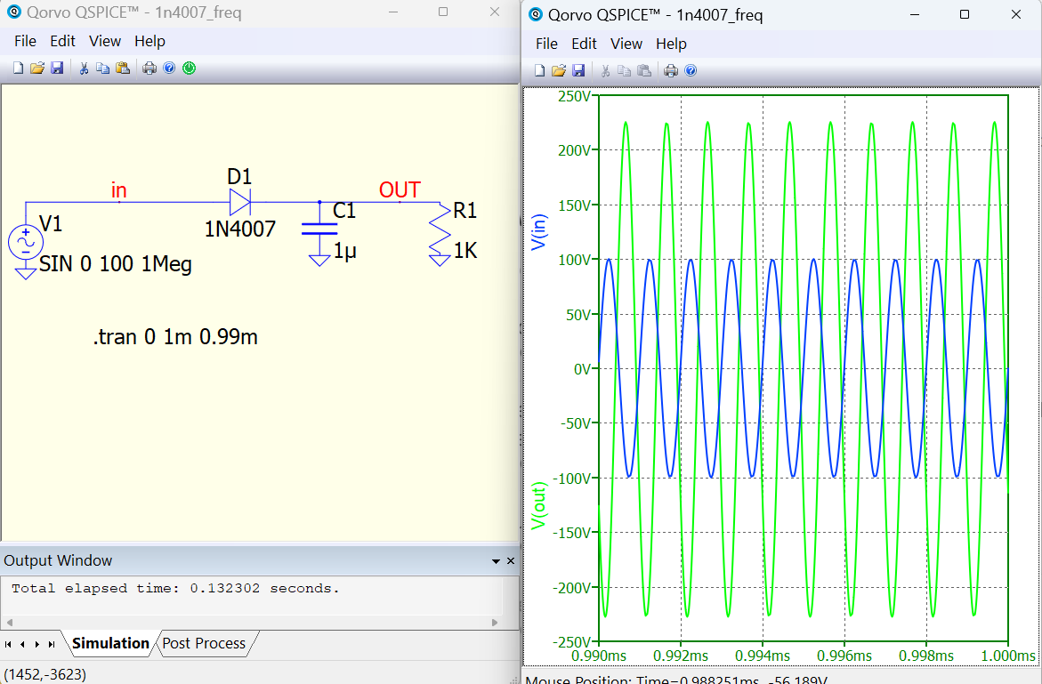
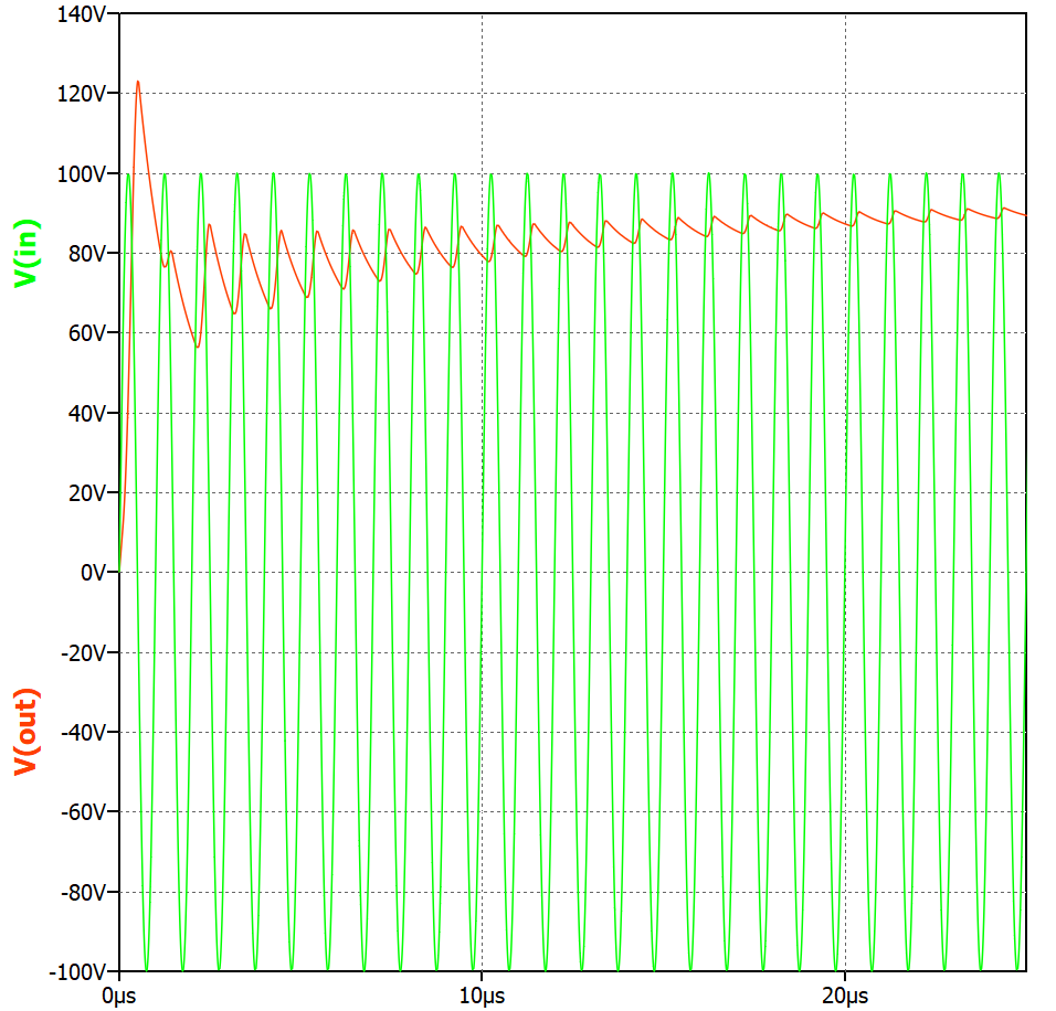
Strange operation of the Qspice diode in the rectifier - there is a higher voltage at the output than at the input. LTspice showed itself worthy.
1n4007_freq.qsch (785 Bytes)
Strange operation of the Qspice diode in the rectifier - there is a higher voltage at the output than at the input. LTspice showed itself worthy.
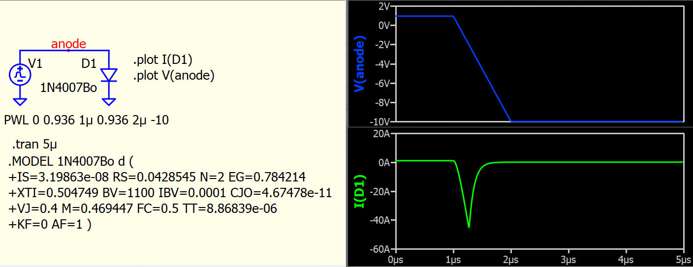
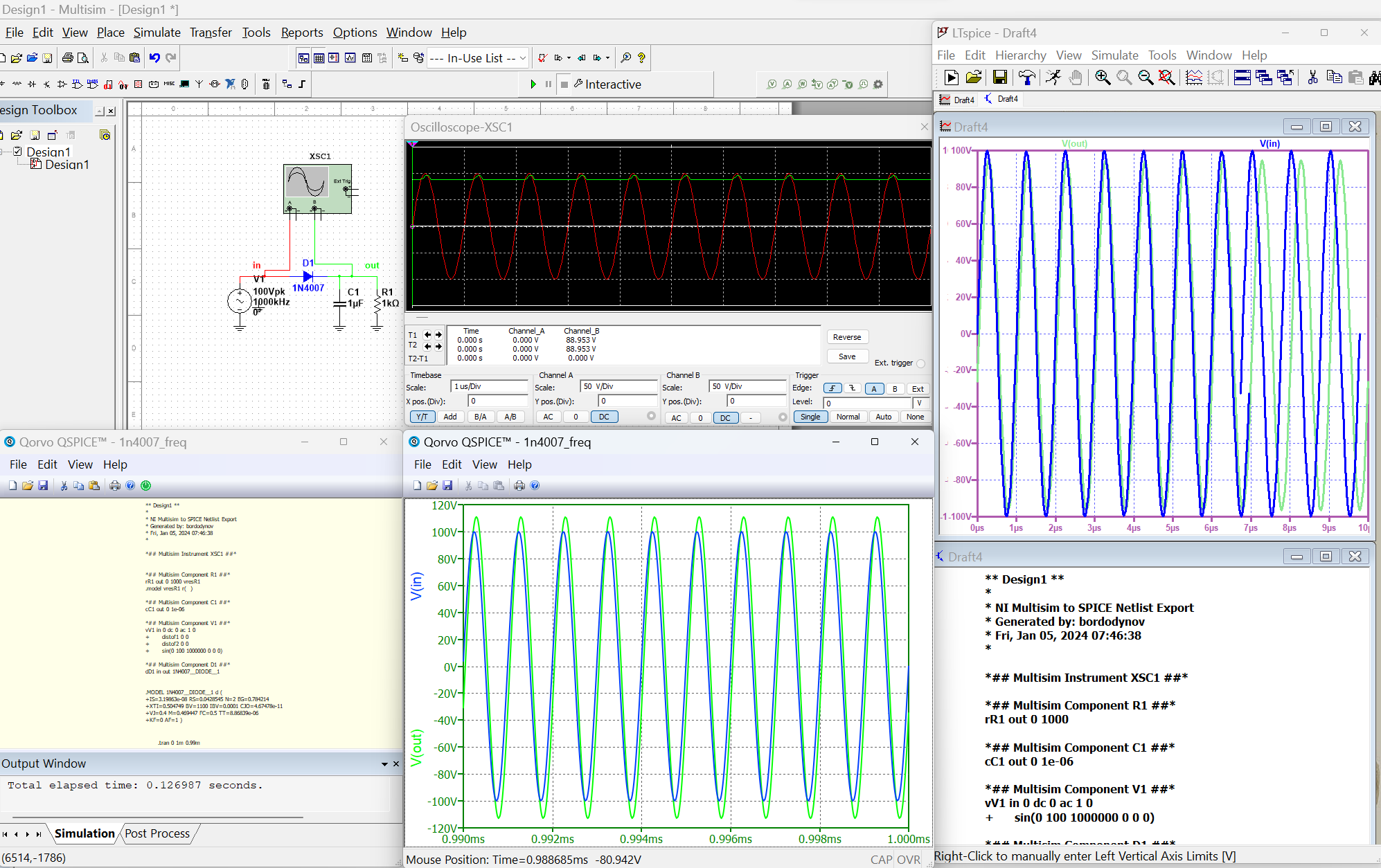
Can we expect 1N4007 still function as a diode at 1000kHz (Period=1us). Revery recovery time parameter TT (transit-time) of 1N4007 is 8.87u in your model, which is much larger than the period of test frequency. LTspice and Qspice simulate reverse recovery differently, this may introduce different in simulation. This is not something practical and seems meaningless for compare. Check the diode current and you see what I mean.
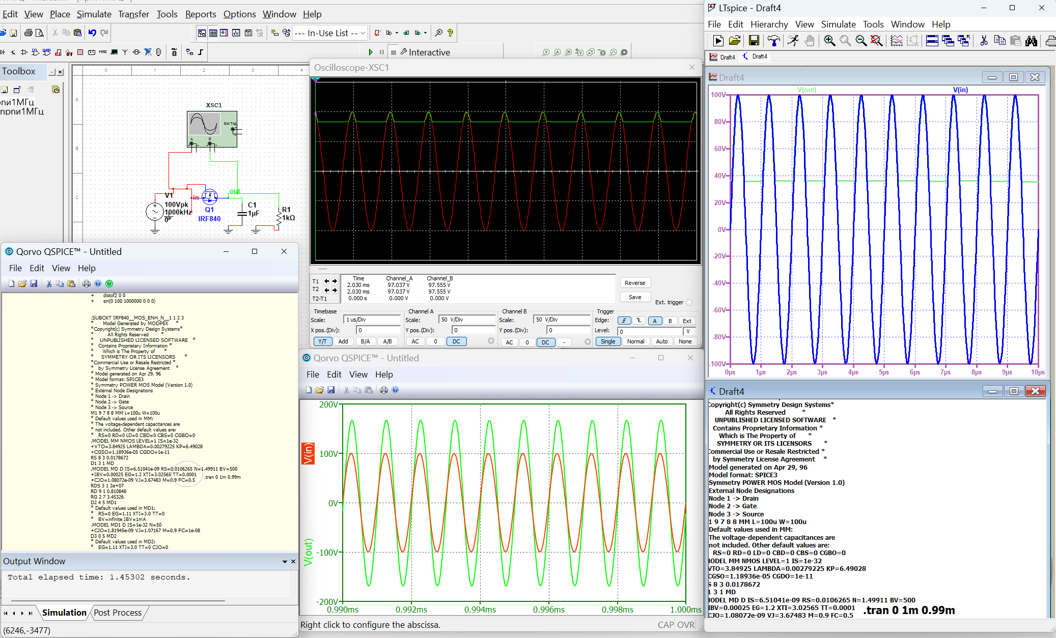
I know very well that the 1N4007 diode has a frequency of no more than 80 kHz. In many Chinese circuits they are used at frequencies approximately equal to 30 kHz. And I don’t need to look at the diode currents, I know that they are large in this simulation. At the same time, everything works in Multisim. I’m the one making fun of him. But I was upset when the voltage at the output of the circuit in the Qspice program turned out to be greater than at the input. Those. despite the incorrect scheme, the program should calculate it correctly. I have doubts about the correctness of diode modeling in Qspice. I previously considered a similar circuit (I was looking for the cutoff frequency of the rectifier at lower frequencies) and used other simulators (5 pieces). And they all gave different results. I expected to get a result similar to the result of LTspice, but it was a bummer. This diode is used in snubber circuits and incorrect consideration of resorption may give incorrect results.
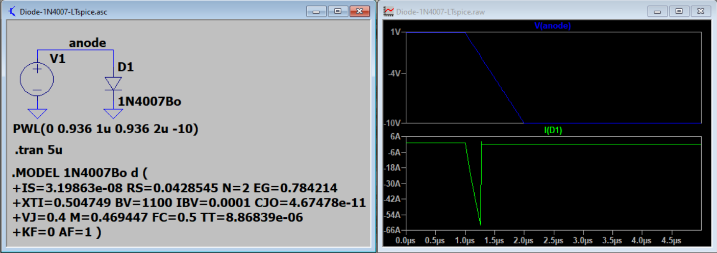
This is a simulation to compare reverse recovery current profile simulate with Qspice and LTspice. It appear to me that Qspice has further improve the modeling of reverse recovery. If your test setup drive to the region that reverse recovery play an important role in calculating the result, different results between Qspice and LTspice can be expected.
My point is, when your circuit is not practical, how you prove LTspice is correct and Qspice is not. You cannot build that circuit to verify your observation. Or in theory or mathematic, when the diode never turn off (as cannot exit from reverse recovery), how the math should suggest the output voltage should be for such a non-linear situation. If portion of math formula has inductive effect, it could form a resonant and output voltage can be higher than input. I just want to say, we just don’t know.
If you remove reverse recovery by forcing TT=0, may be you can get similar result from different simulators in your simulation. From Multisim simulation result, it seems it just not model reverse recovery. Not sure, but you can build this test circuit to test for reverse recovery.
I am more curious with why always getting so angry
see this post: