Hello,
I start to test your software. I am very happy.
But when i would lke to use step param with a parameter into a spice model
For example, i would like to change the parameter : VTO (VGS th)
i change into spice model VTO = {VGSTH} file.
and i write .step parameter VGSTH file 0.65 1 1.5 2
it’s run with spice, but with qspice, i have this warning
Warning: Ignoring unknown model parameter “VGSTH” in .MODEL NMOS•X´q1 NMOS LEVEL•X´q1= 3 VMAX•X´q1= 1E+006 ETA•X´q1= 0 VTO•X´q1= {VGSTH•X´q1} TOX•X´q1= 6E-008 NSUB•X´q1= 1E+016 KP•X´q1= 0.4654 KAPPA•X´q1= 1E-015 U0•X´q1= 400.
MOSFET M1•X´q1 has W=1e-06 which is smaller than can is be realistically modeled with a level 3 equations.
And i don’t have possibility, also, to have all graph with all parameter
Is it possible ? Thanks for all
Upload you simulation file and library (if any). If lib is .lib, you can rename to .txt for upload in forum.
Hello KSKelvin for the moment i can not upload files, because i am a new user.
File 2N7002.lib
*---------- 2N7002 Spice Model ----------
.SUBCKT N7002 10 20 30
M1 1 2 3 3 NMOS L = 1E-006 W = 1E-006
RD 10 1 0.976
RS 30 3 0.001
RG 20 2 160.6
CGS 2 3 2E-011
EGD 12 0 2 1 1
VFB 14 0 0
FFB 2 1 VFB 1
CGD 13 14 5.9E-011
R1 13 0 1
D1 12 13 DLIM
DDG 15 14 DCGD
R2 12 15 1
D2 15 0 DLIM
DSD 3 10 DSUB
.MODEL NMOS NMOS LEVEL = 3 VMAX = 1E+006 ETA = 0 VTO = {VGSTH}
- TOX = 6E-008 NSUB = 1E+016 KP = 0.4654 KAPPA = 1E-015 U0 = 400
.MODEL DCGD D CJO = 1.2E-011 VJ = 0.6 M = 0.6
.MODEL DSUB D IS = 6.808E-010 N = 1.576 RS = 0.1408 BV = 72 CJO = 8E-012 VJ = 0.401 M = 0.614
.MODEL DLIM D IS = 0.0001
.ENDS
*Diodes N7002 Spice Model v0 Last Revised 2017/2/9
i verify also on my new symbol N7002, the symbol property, into the library file tabs: i have
|.SUBCKT N7002 10 20 30\nM1 1 2 3 3 NMOS L = 1E-006 W = 1E-006\nRD 10 1 0.976\nRS 30 3 0.001\nRG 20 2 160.6\nCGS 2 3 2E-011\nEGD 12 0 2 1 1\nVFB 14 0 0\nFFB 2 1 VFB 1\nCGD 13 14 5.9E-011\nR1 13 0 1\nD1 12 13 DLIM\nDDG 15 14 DCGD\nR2 12 15 1\nD2 15 0 DLIM\nDSD 3 10 DSUB\n.MODEL NMOS NMOS LEVEL = 3 VMAX = 1E+006 ETA = 0 VTO = {VGSTH} TOX = 6E-008 NSUB = 1E+016 KP = 0.4654 KAPPA = 1E-015 U0 = 400\n.MODEL DCGD D CJO = 1.2E-011 VJ = 0.6 M = 0.6\n.MODEL DSUB D IS = 6.808E-010 N = 1.576 RS = 0.1408 BV = 72 CJO = 8E-012 VJ = 0.401 M = 0.614\n.MODEL DLIM D IS = 0.0001\n.ENDS
`
and into my schematic i put this
.tran 0.05m
.plot V(Out)
.set param VGSTH list 0.65 2
i have only one plot of V(Out)
Thanks a lot
If you want to use a .subckt library and change its parameter value from the parent schematic, here is the method I use:
- (Not necessary) Instead of using an auto-generated symbol with an embedded .subckt, I prefer to call the library for use. This makes it easier for me to test the effects of other parameters by modifying the .lib file instead of having to locate and change them within the embedded .subckt. To convert an auto-generated symbol that can call a library file, right click on symbol > Show Symbol Properties, and delete anything in the field of “Library File”.
- To achieve the desired functionality, modify
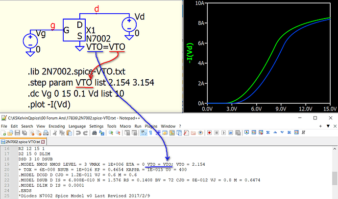
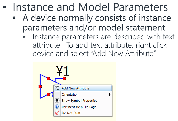
VTO = 2.154 to VTO = VTO of .subckt in the library file. In the parent schematic, add a third attribute to the subckt symbol (right-click on the symbol and select “Add New Attribute”) and name it as VTO=<value>. This will allow you to modify VTO from the parent schematic.
- Now, since you want to step this
VTO parameter, the final step is to use the .step command with VTO. Here is an example for your reference.
In short, to pass a parameter from parent to subckt, you need the subckt to have a parameter=<value>, and the method to add that from parent level is to add an attribute to symbol. I guess this is what you missing.
Sorry that sometime I saw new user can upload files, I am not so sure the rule that when forum allow a new user to upload files.
2N7002.spice-VTO.txt (725 Bytes)
Parent.2N7002.qsch (2.4 KB)
1 Like
Hello KSKelvin
Yes your method is better. Passing this type of parameter makes the diagram much clearer.
and what’s more it works very well
I will follow this method for another parameter.
Thanks a lot
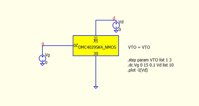
@KSKelvin how did you create a second attribute? It’s seems to be impossible for me.
I’m trying to do basically the same but for this subckt MOSFET instead:
.SUBCKT DMC4029SK4_NMOS 10 20 30
*     TERMINALS:  D  G  S
M1 1 2 3 3 NMOS L = 1E-006 W = 1E-006
RD 10 1 0.008754
RS 30 3 0.001
RG 20 2 1.7
CGS 2 3 1.04E-009
EGD 12 0 2 1 1
VFB 14 0 0
FFB 2 1 VFB 1
CGD 13 14 6.6E-010
R1 13 0 1
D1 12 13 DLIM
DDG 15 14 DCGD
R2 12 15 1
D2 15 0 DLIM
DSD 3 10 DSUB
.MODEL NMOS NMOS LEVEL = 3 VMAX = 4.62E+005 ETA = 0.0001 VTO = 2.455
+ TOX = 6E-008 NSUB = 1E+017 KP = 49.07 KAPPA = 1E-015 U0 = 400
.MODEL DCGD D CJO = 2.703E-010 VJ = 0.2734 M = 0.3551
.MODEL DSUB D IS = 2.278E-010 N = 1.242 RS = 0.007361
+ BV = 50 CJO = 2.302E-010 VJ = 0.3812 M = 0.5232
.MODEL DLIM D IS = 0.0001
.ENDS
This is how to add attribute. To delete it, mouse cursor hover that attribute and press “delete”.
Thank you @KSKelvin, by the way it also seem like you can include it like this
“.SUBCKT DMC4029SK4_NMOS_VTO 10 20 30 VTO=VTO”
by adding “VTO=VTO” before importing the model.
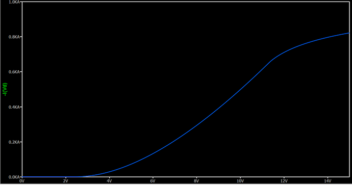
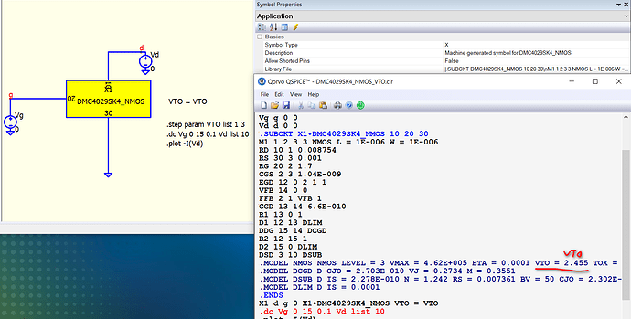
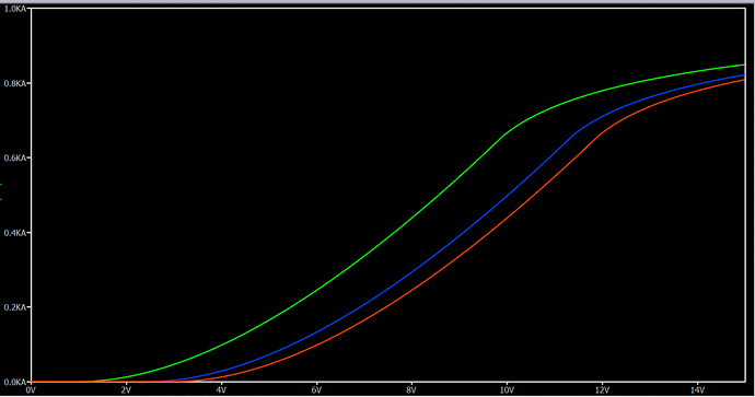
I tried to replicate the method and watch if the VTO step is carried over to the model in the simulation, however it seems like what ever VTO value I put in the list, the result stays the same.
I’ve included the simulation
DMC4029SK4_NMOS_VTO.qsch (3.1 KB)
If you go through my example, I actually modified the original model with VTO=VTO, such that I can pass the parameter “VTO” into the .model during simulation.
In your case, VTO = 2.455, that why .step VTO has nothing pass into the sub-circuit.
I hope this can be more clear. Having model and variable parameters to be the same may be a bit confusing. Now, I changed .step to use parameter “var”.
And, the .subckt is not embedded, but just as a netlist (text) in schematic.
What you have to do, is to modify sub-circuit netlist, with VTO=var. And now you can sweep this parameter. This workflow is easier if you want to test effect of different model parameters.
Parent.NMOS-SUBCKT.qsch (3.7 KB)
1 Like
@KSKelvin Thank you very much! I see the problem now, I think it was my spice syntax knowledge that misleaded me. I think the mistake I did was not realizing that “;” in “VTO=VTO; VTO=2.154” actually commented everything out after it, on the same row.
I got an expected result now, thank you.
Great! I believe I did not provide a very good example in March, as naming a .step parameter the same as a model parameter can be misleading.
