Stable mean but large variation for DS TWR using DW3220-based UWB node

Hi all

I’m currently trying to reduce the variation of the distance calculated with asymmetric DS TWR.

I’m currently using a custom DW3220-based UWB node (The git repo for it can be found at https://github.com/ETH-PBL/UWB_DualAntenna_AoA) for a project.

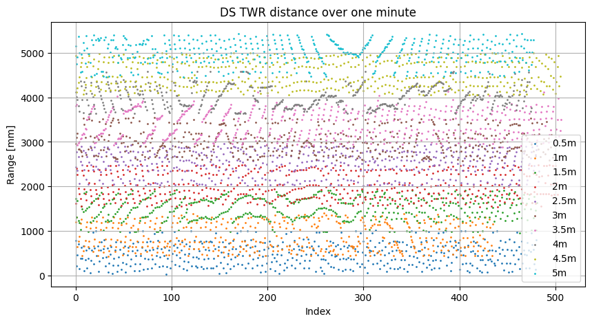
I have done some modifications to the firmware presented in the repo such as reducing the transmission delay to 1 ms and performing proper antenna calibration, in order to improve on the readings. As a result, over a test of one minute, the mean of the measurements stabilize to be around ±10 of the true value.

However, the variation is still quite large, where the distance measurements can vary by around ±50 cm. This is shown in the plot below.

I have seen a lot of material that suggests the DW3220 should have precision within ±10 cm, so I assumed the variance would be smaller.

I have seen a lot of applications notes regarding how to improve the mean using antenna calibration and limiting the effects of clock drift by using smaller and equal transmission delay times, but none about reducing the variation.

So finally my question is: What parameters should I adjust to improve the variation? Would a longer preamble help? higher transmission power? Lower data rate? Or is it just normal to have such a large variation in your DS TWR measurements?

Finally, here is my configuration settings, if they are of interest

static dwt_config_t config = {
5,
DWT_PLEN_128,
DWT_PAC8,
9,
9,
1,
DWT_BR_6M8,
DWT_PHRMODE_STD,
DWT_PHRRATE_STD,
(129 + 8 - 8),
(DWT_STS_MODE_1 | DWT_STS_MODE_SDC),
DWT_STS_LEN_256,
DWT_PDOA_M3
};

In advance, than you for your help.

I use an asymmetric DS-TWR and, with a lot of tuning and calibration, can get a mean point to point error of under +/- 2cm from 1 m to 50 m in range. This is under good conditions (open field, several meters above the ground at both ends etc… The standard deviation in that situation is in the 3cm region. This is custom hardware, custom firmware and a lot of fiddle factors and corrections applied but most of that is for the last few cm of accuracy, getting 10 cm most of the time isn’t too tricky after antenna delay calibration. And that’s a constant offset not a changing value like you are seeing.

Your data shows clear trend line patterns that to me imply a beat pattern, some sort of rounding issue or other value that is not getting correctly accounted for. e.g. if you only used the top 32 bits of a 40 bit value then you would get what looks like a random error. If you then repeated the measurements at a fixed rate you’d get a pattern in that error related to the measurement rate and the internal clock rate. The error would change each time by the period between measurements measured in internal clock cycles modulo 256. As things warmed up and clocks drifted this pattern would slowly change over time giving results similar to what you are seeing.

However a very crude back of the envelope calculation implies that you are seeing around 7 bits worth of error in the timer rather than 8 so it’s probably not exactly that.
You’re not converting time values to floats too early and introducing rounding issues there are you?

Either way I’d work out exactly how wide you measurement band is, convert that into internal clock cycles and work out how many bits of the clock that would represent and look through your code to see if there is anywhere that you have a potential to round by that much. Also look for anywhere that you convert from integer clock cycles to floating mount and verify that the values at that point are small enough that the floating point resolution isn’t going to introduce meaningful rounding errors.

1 Like

Thank you very much for your response Andy. I did not expect something that went that much into detail, but I’m incredibly happy that you did.

I think it is very likely that it might be due to some rounding errors - I’ll have to look into the firmware more, but at a glance I can see that the ETH guys have a different approach to calculating the ToF compared to the Decawave DS TWR example. I haven’t been able to make the DS TWR example work reliably due to odd timeout errors so I haven’t been able to compare their performance properly.

I’ll respond if I figure something out - sadly my project is reaching its end, so I don’t know if I have time for making more measurements. But anyways, I’m very happy for your help!