Hello,
I am attempting to learn how to manage imported models and design symbols. To that end, I’ve started with a MOSFET I’ve simulated extensively in LTSpice, the RH6L040BG.
The following circuit yields the very strange slow turn off behavior
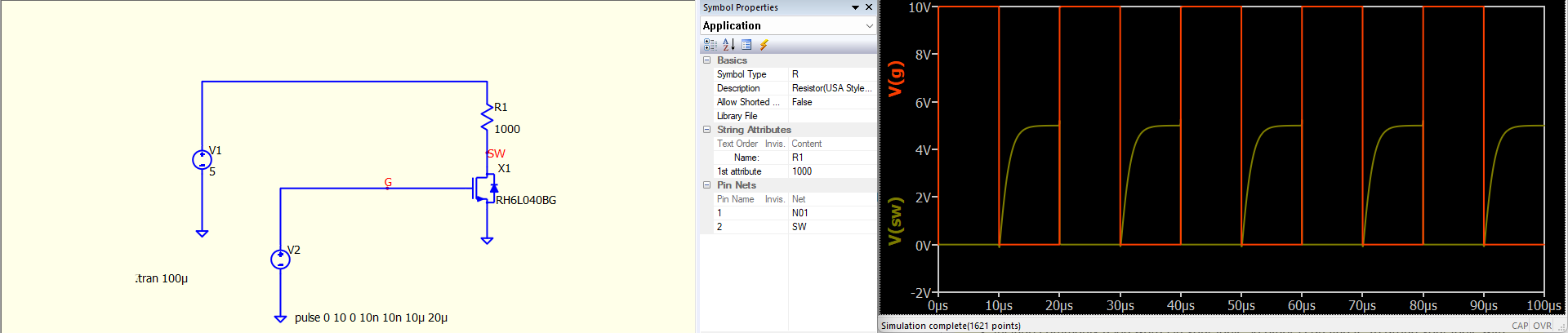
If I decrease R1 to 10ohms, the turn off time improves significantly. I am really unclear as to why this would be.
Here is the subckt definition for the mosfet:
.SUBCKT RH6L040BG 1 2 3
M1 11 22 3 3 MOS_N
D1 3 1 DDS1
R1 1 11 RTH 4.5653E-3
RG 2 22 10.2
D14 22 11 DGD1
.MODEL MOS_N NMOS TNOM = 25
+ LEVEL = 3
+ L = 2.0000E-6
+ W = 1
+ KP = 284.79E-6
+ RS = 0
+ RD = 0
+ VTO = 2.3551
+ TOX = 2.0000E-6
+ CGSO = 1.3386E-9
+ CGDO = 14.103E-12
+ CBD = 0
+ N = 2
+ GAMMA = 1.1618
+ ETA = 1.0000E-3
+ KAPPA = 0.2
+ NFS = 21.936E+9
+ XJ = 1.0000E-6
+ UO = 377.69
+ VMAX = 50.000E+3
.MODEL DDS1 D TNOM = 25
+ IS = 1.4839E-12
+ N = 0.9308
+ RS = 1.3025E-3
+ IKF = 0.2056
+ CJO = 1.5386E-9
+ M = 0.9495
+ VJ = 6.8496
+ XTI = 2.105
+ BV = 60
+ TT = 24.100E-9
.MODEL RTH RES TNOM = 25
+ TC1 = 6.3368E-3
+ TC2 = 0.2157E-6
.MODEL DGD1 D TNOM = 25
+ N = 10.000E+3
+ CJO = 170.50E-12
+ M = 2.9893
+ VJ = 28.732
+ FC = 0.02
+ T_ABS = 25
.ENDS