Sleep Mode Swap During Operation | Power Consumtion

Hi,

I am new to UWB communication. I want to buy TREK1000 but have a few design questions in mind if someone can address it. In my RTLS application, I want tag (TX) to be as low power consuming as possible. I don’t need a high data rate, accuracy or precision of localization. Moreover, my application will be in LoS in open field.

  1. For the tag, can I switch between sleep mode to lowest power TX mode during operation (in real-time) from host processor, in TREK1000 evaluation boards? The motivation is to not run tag in TX mode all the time and save some power and energy requirements by having a duty cycle such as 95% sleep and 5% TX operation.

  2. Does the TREK1000 boards API provide data communication commands? Along with positioning information, I want to send sensory data from tag to anchors. Does API provide this functionality?

  3. What’s the power consumption of TREK1000 boards in lowest power TX mode (mode 1)? In DW1000 data sheet, it is mentioned that TX mode consumes max 70 mA. I couldn’t find information on current consumption of evaluation board. At one point, it is written if power source is USB, it should at least be capable of supplying 250 mA. Does this mean minimum power consumption of TREK1000 board (in TX mode 1) is 250 mA? Please guide.

  4. DW1000 user manual tells about parameters of mode 1 such as data rate and sequence length, all of which indirectly affect range and accuracy. Can someone please give a rough estimate of what range and accuracy I should expect for a tag running in TX mode 1 in open field LoS application?

Thanks.

The TREK1000 contains 4xEVB1000. The main purpose of the TREK is to give an instant tracking, locating or geo-fencing setup for evolution.

It would be unrealistic to use the EVB1000 for serious power usage investigation as the power efficiency of a PCB in general depends on various other components on the board and their layout. The power consumption of the complete EVB1000 will ofcourse require more power then what the IC itself would require (as per datasheet) . So at any point the EVB1000 would require at least (ICcurrent + MCUcurrent + DC/DCcurrent and more see EVB schematic).

The TREK is for evaluation. To develop a power efficient TAG with long battery life one may pick a power efficient MCU , pick components carefully and follow the guidelines in APS001 on System related aspects of DW1000 power consumption

For the tag, can I switch between sleep mode to lowest power TX mode during operation (in real-time) from host processor, in TREK1000 evaluation boards? The motivation is to not run tag in TX mode all the time and save some power and energy requirements by having a duty cycle such as 95% sleep and 5% TX operation.

Yes, you can by using the hardware. But you may need to change the software a bit. In TREK, the TAG does go to sleep between ranges with the anchors, but you may need to change some of the timings for wakeup and sleep and start-up as the timings used in TREK SW are default values.

Best is to look at the TREK source code where this is explained and again, check APS001

Does the TREK1000 boards API provide data communication commands? Along with positioning information, I want to send sensory data from tag to anchors. Does API provide this functionality?.

Yes, see IC datasheet, but one could also have a look at our example sw ex_10 on the use of GPIOs

What’s the power consumption of TREK1000 boards in lowest power TX mode (mode 1)? In DW1000 data sheet, it is mentioned that TX mode consumes max 70 mA. I couldn’t find information on current consumption of evaluation board. At one point, it is written if power source is USB, it should at least be capable of supplying 250 mA. Does this mean minimum power consumption of TREK1000 board (in TX mode 1) is 250 mA? Please guide.

It could well be 250mA. As mentioned earlier, the EVB1000 are not optimised to use minimum current consumption.

DW1000 user manual tells about parameters of mode 1 such as data rate and sequence length, all of which indirectly affect range and accuracy. Can someone please give a rough estimate of what range and accuracy I should expect for a tag running in TX mode 1 in open field LoS application?

What range would you require? Channel 1 might in theory give you the longest range , but channel 2 and 5 may well be as good.

Data rate will also determine the range. 110kb/s could give you the furthest range, while 8.6Mb/s the shortest. 850kb/s could give you similar or better range then 110kb/s in practise, eg when smart power can be used.

Regards
Leo

Thank you @DecaLeo for the comprehensive reply. I require a range of 200-300 meters.

Can I have a tag with DWM1000 module instead of DW1000 EVB? I can have 3 anchors using 3 evaluation kits from TREK1000 but for the tag, power consumption and size (weight) is a big design factor. If I can use a DWM1000 with host processor as a tag in conjunction with 3 DW1000 EVBs for RLTS, that’d be optimal design.

Can you give some pointers how to make that happen? Will I be able to utilize readily available tracking and locating features of TREK? Thanks !

This is not an easy range to achieve using UWB and remain within regulatory power levels, so I would concentrate first on this issue since it can be show stopping otherwise. I suggest you test whatever hardware you are considering in actual conditions to see true realistic range.

I know it can be done with an excellent antenna, an excellent LNA preamplifier, and adjustments to RF parameters. I don’t think it can be done with stock modules, regardless of settings, assuming you aren’t violating regulatory limits.

One big win would be if you can use directional antennas on the anchor array. Sounds like you are working a sports field or similar outdoor venue where the anchors are around the perimeter of the field. For example, a cricket pitch where the boundary is ~75 meters from the center, plus stands, would fit your description. Anchors can end up 150 meters from the center, thus needing 225 meters to read a tag across the field. We have built systems that can do this.

An antenna which is directional to the field can have higher gain, say 10 dB, and that can help a lot with receiving tags. This only works when you know the anchor only needs a limited field of view. This is how most of our sports installs are done, including a cricket pitch. The directional antenna also helps reduce interference by reducing pick up of signals not coming from the field. One needs to be careful with directional antennas, many of them have poor time domain response which hurts reception.

Note that this is only workable when you are doing TDoA style location (tag transmits, doesn’t have to receive, anchors compute location by arrival timestamps). This is because the tag antenna will never be as good as the anchor, and it will be omnidirectional in general. So any sort of TWR based scheme will fail in these long range setups because the tag can’t hear the anchors even though the anchor can hear the tags. Since anchors need to be precisely synchronized for TDoA to work, the anchors have to transmit to each other, which can get tricky if their antennas are focused on the field. We have built custom anchors with multiple antennas (two directional, one omni) to address this issue.

In short, I am fairly certain your range requirements are a challenge that won’t be satisfied with off the shelf stuff.

There are other technologies besides UWB that can measure range at longer distances, but they are far less accurate (1-2 meters) and far less capacity (less than 100 locates per second, maybe much less). If your application can tolerate that, might consider something other than UWB. Most applications can’t, however.

Given the outdoor use case, an RTK GPS system can provide 5 to 10 Hz positions per tag at ~3 cm accuracy. This has gotten a lot less costly lately, but still not cheap exactly, and the size and power requirements don’t sound compatible with your application. Does require some sort of radio for delivery of corrections and upload of locations from the tag.

Mike Ciholas, President, Ciholas, Inc
3700 Bell Road, Newburgh, IN 47630 USA
mikec@ciholas.com
+1 812 962 9408

1 Like

Thank you @mciholas. This is important as my anchors won’t be at a larger distance to each other.

I plan to have 3 anchors on an Unmanned Aerial Vehicle (UAV) and the tag is a floating sensor suite on water body. While for anchors, relative position to each other would be fixed but position of tag will move significantly with respect to anchors (UAV).

My application is indeed TDoA.

Can you please mention some technologies? I couldn’t find reliable solutions for RTLS using BLE. My application can tolerate less precision and frequency. Range and power requirements are important.

GPS is too power consuming for my application.

There may be regulatory issues with this since UWB is banned from operation on flying machines in some jurisdictions, notably US and Europe.

FCC 47 CFR 15.250: “Operation on board an aircraft or a satellite is prohibited.”

ETSI EN 302-065-1: “the UWB transmitter equipment conforming to the present document is not to be installed at a fixed outdoor location, for use in flying models, aircraft and other forms of aviation.”

If the anchors on the drone transmit at all, you would be in technical violation of the above rules. I’ve seen quite a few drone uses of UWB, so adherence to these rules is not universal.

I am surmising your application is a data collection drone which flies over a number of floating tags and downloads data from them. You don’t need super precision because the drone is GPS equipped and you only need to know the tag location relative to the drone to record the tag location, which I presume is desired data. So the tag doesn’t need a GPS receiver to be located with roughly GPS precision if the drone can locate the tag accurately enough relative it itself.

Given your anchor array of 3 on one drone, it seems you wish for distance and bearing to a tag as your base location capability. 3 anchors are needed to disambiguate direction without having ambiguity, at least in a static setup.

But given you have a drone, and assuming tags don’t move quickly, there are navigation ways to do this with one anchor. Have the drone fly to 3 points in the sky, take distance measurement, and from that you simulate having more anchors and can use a larger baseline. Once location is computed, fly to tag position. You can criticize this for extra energy to fly around in a pattern, but reducing the weight by two anchors and not having to power them does save energy, too. The flight path can be optimized for energy as well using a zig zag motion towards the tag which provides constant update of tag location as you go.

TDoA is very poor at measuring distance between an array of anchors and a tag when the tag is outside the lateral bounds of the anchor array. I would not expect a drone of reasonable size with 3 anchors to be able to measure the distance to a tag reliably at all using TDoA. To get reliable distance, you will need a round trip of some kind, both sides transmit to the other, such as in TWR.

Any RSSI based solution, like BLE, is condemned to failure, it just won’t work well enough to be useful. BLE 5.1 claims to have direction finding capability, angle of arrival (untested by us as of yet). That may be something to look into if angle is enough to make your system work, which I doubt.

Semtech SX1280 is a LoRa based chipset with ranging. We haven’t tested it as yet, but there is some encouraging data. 2.4 GHz, precision varies with settings, but sub 1 meter seems possible, long range. Complex to understand the tradeoffs in air time, power, and accuracy, but looks like very interesting technology. They have demonstrated ranging at 2 km.

Two other choices we have used but aren’t that easy to integrate are:

Nanotron makes a chirp based chipset, nanoLOC. 2.4 GHz, about 1-2 meters accurate (we’ve tested it), can go long range since you can use more RF power in 2.4 GHz band.

MicroChip/Atmel has phase shift ranging technology in their AT86RF233 chips, also 2.4 GHz, also about 1-2 meters (we tested it and developed our own ranging algorithm for it). Involves stepping through some frequencies so takes some time to measure range. Atmel didn’t heavily promote this feature for some reason.

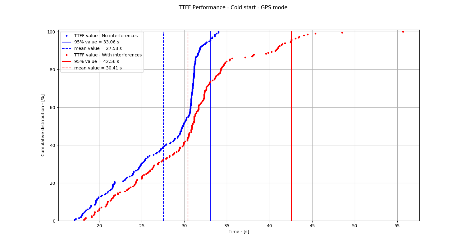
I suspect it isn’t, if you use it carefully. For example, leave it off until a low power radio signal says to activate it, get a fix, report results, turn it off. Your time to first fix may be too long, but that’s under 30 seconds in most cases these days, and power consumption is down to 60 mW or so, so you don’t use a lot of energy at all. With good sky visibility, will lock on fast. Does add cost to your tags, but GPS chipsets are getting quite cheap these days, under $10.

I’m wondering if the drone is really required if you had a very long range radio like LoRa and a low duty cycle GPS. Wake up, read location, sensors, send LoRa signal, sleep. Could be very low power.

Yeah, I know, having a drone is cool. :slight_smile:

Apologies if I have misunderstood your application. I have to fill in the unknowns to provide useful suggestions.

Mike Ciholas, President, Ciholas, Inc
3700 Bell Road, Newburgh, IN 47630 USA
mikec@ciholas.com
+1 812 962 9408

1 Like

Thank you @mciholas. These are really valuable suggestions.

The only issue I have with the GPS is the startup time, are you completely sure that it takes only less than 30 s to get a first fix reliably? Because normally you would need to download ephemerides, etc. from the satellite, and that could take up to 2 hours. Are these chips assisted by 4 G in some way? Any GPS you can share?

Modern GPS chipsets do a fantastic job of reducing time to first fix (TTFF), a parameter that drives many applications. They have so many receiver channels that they can search for satellites very quickly, and the newer satellites are more powerful leading to faster capture times. The almanac and ephemeris are sent in parallel on the satellites with data striping so you can download the entire data quickly even though it takes 12.5 minutes for one satellite to do it by itself. It should never take 2 hours.

Here’s a test:

https://www.skydelsolutions.com/en/resources/app-notes/app-note-gnss-basic-tests-ttff/

The punch line is this chart for a cold start, one with no history or data on board to help it start, and without a data link to get data from some other path:

By 35 seconds or so, most units have locked on. If the unit has almanac (valid for 180 days), and ephemeris (valid for 4 hours), it can lock on in a few seconds. In your use case, you can probably afford the power to boot the GPS every 4 hours, get a lock and new ephemeris, and go to sleep. Then your relock time is very quick when the drone contacts the tag/sensor.

I’ve not used it, but this looks interesting:

https://www.u-blox.com/sites/default/files/ZOE-M8B_DataSheet_(UBX-17035164).pdf

Cold start time is 26 seconds, hot start time is 1 second (have time, almanac, ephemeris, and haven’t moved more than 100 km). It can do this with a 72 channel receiver which means parallel download of data among all visible satellites.

It has options for aiding (download almanac and ephemeris via radio link) which reduces TTFF.

If you can tolerate a cold start, just turn it off until you need it. Then the power is nothing when not in use. How much power you use is determined by how often you want a location.

If you want a more responsive system, you can keep the GPS “hot” with almanac, ephemeris, clock, and last known location. This allows a “hot” start and captures in a second or so. To do that, you power it up for 1 minute every two hours, which should be much more than you need since that would do a cold start. The data sheet says that will be 81 mW during acquisition. The datasheet says you need 36 uW otherwise to keep RTC and chip state. Net result is an average power usage of 711 uW of energy. So can your application handle 0.7 mW average and 81 mW peak power usage?

The exact design will depend on the use case you need, how many locates you need to do, and what response time you need for the location.

Mike Ciholas, President, Ciholas, Inc
3700 Bell Road, Newburgh, IN 47630 USA
mikec@ciholas.com
+1 812 962 9408