Singular matrix in .subckt

Hello

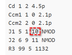
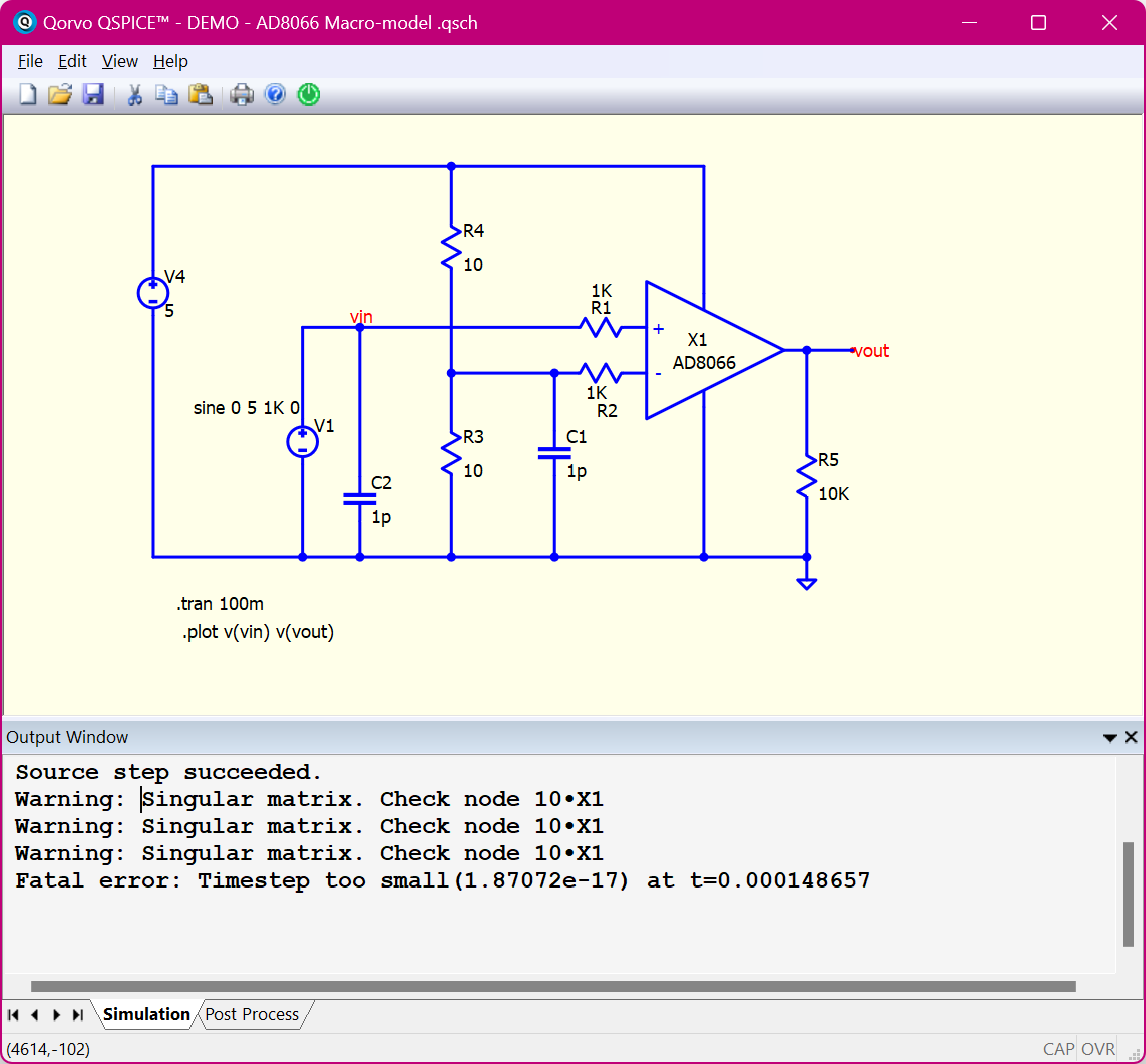
I am striking out today with moving models over from LTspice to Qspice. I am using a spice model for an AD8066 op-amp and I think qspice is trying to tell me that there is a singular matrix in the model? I have X1 but there is no node 10 in my circuit, so is the issue in the .subckt node 10? How would one be able to see that node?

* AD8066 Spice Model
* Description: Amplifier
* Generic Desc: Dual low-cost high-speed FET input amp
* Developed by: VC
* Revision History: 08/10/2012 - Updated to new header style
* 1.0
* Copyright 2012 by Analog Devices, Inc.
*
* Refer to http://www.analog.com/Analog_Root/static/techSupport/designTools/spiceModels/license/spice_general.html for License Statement.
* Use of this model indicates your acceptance with the terms and provisions in the License Statement.
*
* BEGIN Notes:
*
* Not Modeled:
*       Distortion is not characterized
*
* Parameters modeled include:
*       Open loop gain and phase vs. frequency
*       Output impedance vs. frequency
*       Output clamping voltage and current
*       FET Input common mode range
*       Slew rate
*       Output currents are reflected to V supplies
*       Vos is static and will not vary
*
* END Notes
*
* Node assignments
*              non-inverting input
*              | inverting input
*              | | positive supply
*              | | |  negative supply
*              | | |  |  output
*              | | |  |  |
.SUBCKT AD8066 1 2 99 50 30

* FET INPUT STAGE
Vos 9 2 1.5m
Cd 1 2 4.5p
Ccm1 1 0 2.1p
Ccm2 2 0 2.1p
J1 5 1 10 NMOD  
J2 6 9 11 NMOD 
R3 99 5 1132 
R4 99 6 1132
R5 10 4 390
R6 11 4 390
I11 4 50 0.87e-3

* COMMON-MODE GAIN NETW0RK
*POLE AT 40 MHz
Ecm 80 15 POLY(2) 2 15 1 15 0 .5 .5 
*C4 82 85 3.54e-12
*R8 80 82 1k

*ZERO AT 40 kHz
Gcm1 15 81 80 15 4e-6
Lcm1 81 82 2e-3
Rcm1 82 15 1k

*ZERO AT 40 MHz
*Gcm2 15 83 81 15 1e-3
*Lcm2 83 84 3.5e-6
*Rcm2 84 15 1k

*ZERO AT 40 MHz
*Gcm3 15 85 83 15 1e-3
*Lcm3 85 86 3.5e-6
*Rcm3 86 15 1k

*ZERO AT 40 MHz
*Gcm4 15 91 85 15 1e-3
*Lcm4 91 92 3.5e-6
*Rcm4 92 15 1k

*POLE AT 30 MHz
*Gcm5 15 87 91 15 1e-3
*Ccm5 87 15 5.6e-12
*Rcm5 87 15 1k

*POLE AT 30 MHz
*Gcm6 15 88 87 15 1e-3
*Ccm6 88 15 5.6e-12
*Rcm6 88 15 1k

*POLE AT 30 MHz
*Gcm7 15 89 88 15 1e-3
*Ccm7 89 15 5.6e-12
*Rcm7 89 15 1k

* GAIN STAGE & POLE AT 17 kHz
Ecc 98 0 99 0 1
Ess 52 0 50 0 1
Eref 15 0 POLY(2) 99 0 50 0 0 .5 .5 
G1 13 15 5 6 0.6
R7 13 15 3.125k
C3 13 15 3n
V1 98 14 1
V2 16 52 1
D1 13 14 DX
D2 16 13 DX

* POLE AT 334 MHz
G2 15 43 13 15 3.777m
R10 15 43 265
C5 15 43 1.8p

* POLE AT 665 MHz
G3 15 53 43 15 7.54m
R11 15 53 133
C6 15 53 1.8p

*POLE AT 665 MHz
G4 15 63 53 15 7.54m
R12 15 63 133
C7 15 63 1.8p

* BUFFER STAGE
Gbuf 15 32 63 15 1e-3
Rbuf 32 15 1000

* OUTPUT STAGE
Vo1 99 90 0
Vo2 51 50 0
R18 25 90 .02
R19 25 51 .02
Vcd 25 30 0
G6 25 90 99 32 50
G7 51 25 32 50 50
V4 26 25 -0.82
V5 25 27 -0.82
D5 32 26 Dx
D6 27 32 DX

Fo1 15 70 vcd 1
D7 70 71 DX
D8 72 70 DX
Vi1 71 15 0
Vi2 15 72 0

Erefq 96 0 30 0 1 
Iq 99 50 5.7m
Fq1 96 99 POLY(2) Vo1 Vi1 0 1 -1
Fq2 50 96 POLY(2) Vo2 Vi2 0 1 -1

.MODEL NMOD NJF VTO=0.13 BETA=100 IS=2.4e-13
.MODEL DX D(IS=1e-15) 
.ENDS


Check node 10•X1 means the node is inside .subckt X1, which is within your model.

image

1 Like

Thanks for the tip, If I wanted to understand that further, do you know of any good books or reference materials that cover .subckt creation and modification?

Possibly in your case, you don’t have to modify the .subckt
I replicated your circuit (not a fully replication), and can run it with two change

  • Add uic in .tran
  • Add .option gshunt = 1e-10

Parent.AD8066 - Topic 16996.qsch (7.7 KB)

However, AD8066 is an opamp, but your circuit is a comparator (drive output to fully saturate at Vdd or Vss), are you sure you are going to build this circuit?
I add an example which is based on datasheet Figure 42 as your reference.

Parent.AD8066 - Datasheet Fig 42.qsch (6.5 KB)

1 Like

For your .subckt question. There is nothing special about .subckt.
If you understand the workflow of spice simulation, you understand what .subckt is.
Spice program in general offers a GUI to convert a schematic into a netlist. What the spice truly refer to is the simulator which run netlist and output its result. (some people create circuit directly as netlist instead of using any GUI)
In short, every thing in your schematic is converted to a netlist. .subckt is a circuit already in netlist format instead of a visual schematic format. Therefore, if you learn netlist format, you can start to analyze .subckt

1 Like

Give you an example. This is .subckt of TL431, which can be download from Onesmi website.
To study a netlist, it is easier by converting its into a schematic. Therefore, I study the sub-circuit netlist and draw its schematic. This is a way to help understand what this .subckt is.
However, many .subckt is very complicated and you may not want to do it.

1 Like

@KSKelvin
Thanks for looking at this and the explanations. I’m at the point where I would like to learn more about the inner workings of spice and this is great info!

Possibly in your case, you don’t have to modify the .subckt
I replicated your circuit (not a fully replication), and can run it with two change

However, AD8066 is an opamp, but your circuit is a comparator (drive output to fully saturate at Vdd or Vss), are you sure you are going to build this circuit?
I add an example which is based on datasheet Figure 42 as your reference.

I see, this is interesting. The AD8066 model looks like it has issues when the input signal pushes the part into saturation. I’m not planning on implementing this circuit physically I was just using it as a test circuit (for a comparator) while pulling part models into my library.

This updated simulation gets stuck at ~7ms when the input signal is > than the rail voltages.

I guess the lesson is, don’t design bad circuits in life or spice : )

@KSKelvin
Thanks for taking the time to detail this info!