Single-anchor 2-antenna PDoA: front/back ambiguity for inside/outside doorway detection

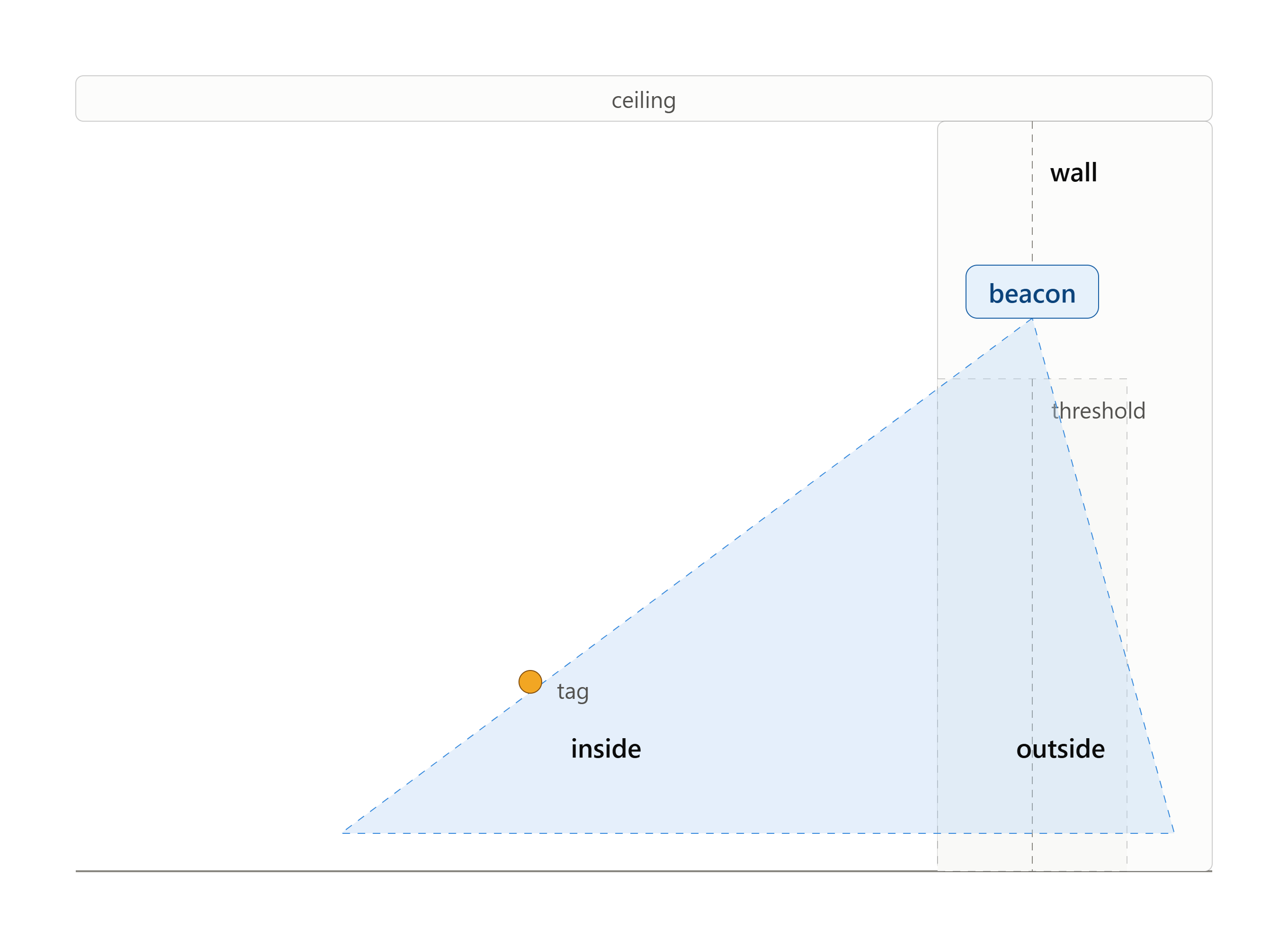
I’m building a wall-mounted single-anchor UWB system to detect whether a tag is inside or outside a doorway, using AoA rather than a fixed threshold gate (tag needs to be tracked even through an already-open door).

Hardware: QM33120W-based custom PCBA, plus a bare Murata Type 2AB EVB (Qorvo QM33120W) running the same firmware, and separately Qorvo’s own official Segger-based reference PDoA firmware; same result on all three.

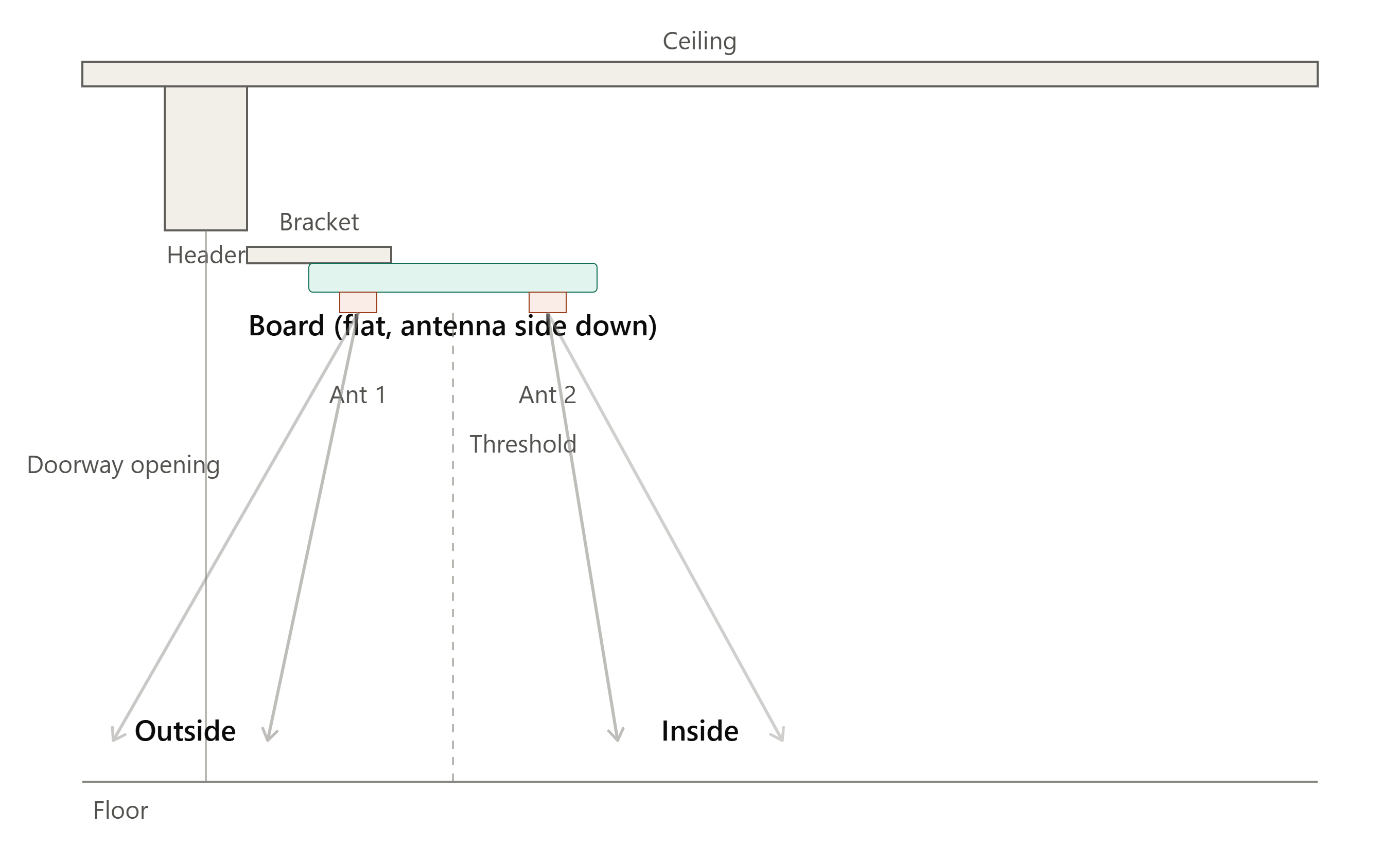
Anchor is ceiling-mounted ~7ft up, antennas facing straight down. With clean, strong RSSI/power, walking or circling inside the home near the anchor produces wild angle swings and false “outside” commits even while the tag is clearly still inside.

Sign convention issue: My expectation is a consistent convention; positive angle = inside, negative = outside, crossing zero at the doorway threshold. In practice, while the tag is unambiguously still inside, I’m seeing both positive and negative angles, correlated with the tag being rotated and moved in random directions/speeds by the person carrying it; not with actual position relative to the doorway. If I hold the tag in the optimal straight forward/antenna on top, everything is fine but when moving/rotating the tag (DW3000), I start seeing different AoA values even when standing in the same place.

Per APH511 (front-back ambiguity), I understand a 2-element PDoA array only measures phase along one baseline axis, constraining the tag to a cone rather than a point, which matches what I’m seeing. Before I move to different hardware, I wanted to ask the community directly:

  1. Has anyone solved single-anchor front/back ambiguity with a 2-antenna QM33120W/DW3000 setup (e.g., antenna geometry, mounting offset, dual-mode ranging) rather than adding a 3rd antenna/second chip?
  2. Any recommended antenna array or mounting configuration for a top-down, overhead-mount use case specifically?
  3. Is there a Qorvo part/module with 3+ simultaneous RX chains for a true second baseline, or is that outside the current QM3x product line?

Appreciate any advice.
Hello,

You mention that the anchor is ceiling mounted. Are the antennas facing down? If so, then there is only front. Back would be the floor above, is it correct?

What antenna design are you using and what is the spacing of your antennas? Did you perform a calibration and create a new lookup table?

Thanks for the quick reply, Akash. Answering in order:

  • Antennas: facing straight down, confirmed. I’ve attached an updated photo of my actual setup for a clearer picture than the diagram.

  • Board: Murata Type2AB EVB (JS-1055, PCB antenna variant) for this round of testing.

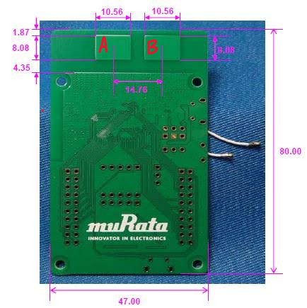
  • Antenna spacing: pulled from Murata’s datasheet, the JS-1055 EVB uses the REMC22003 PDoA antenna reference design, pad spacing ~10.56mm center-to-center per their antenna drawing.

  • Calibration/LUT: no, I haven’t done either yet. The Murata Type2AB EVB board comes with Frequency, Tx power and Antenna delay calibration for each device.

On the calibration point, want to make sure I’m not missing something, but as I understand it (Note 7 in the simple_tx_pdoa example), the calibration is a single fixed offset: measure raw PDOA at a known 0° boresight, subtract that constant from all readings going forward. That would correct a static bias, but it wouldn’t explain what I’m seeing, which is the sign flipping between + and - while the tag stays in the same spot and rotates. A fixed offset can’t produce that kind of instability. Is there a calibration step beyond the single-point offset that I’m not aware of, something that addresses variance rather than bias?

What I’m actually trying to solve: the polarity flips themselves. Standing still, same position, same orientation relative to the anchor. I still see the angle occasionally jump sign, which reads as a false “outside” even though the tag hasn’t moved. Two things I’m trying to rule in or out:

  1. Multipath: ceiling/wall reflections corrupting the phase measurement, especially since my mount is close to a ceiling and a nearby wall.

  2. RF switching artifacts: the QM33120W time-multiplexes a single RX chain across the two antennas rather than sampling both simultaneously. Could switching-domain timing during tag rotation/movement introduce phase errors that look like this, or is that switching fast enough relative to motion that it shouldn’t matter in practice?

Any pointers on isolating which of these (or something else entirely)? I attached a log of samples taken about 20ms apart where I am holding the DW3000 tag and walking around only inside. Each line is a induvial AoA measurement. The inside angles should only be positive but I am seeing the angle measurements flipping and changing drastically.
qorvo_log_flipping_angle.txt (2.3 KB)

Two things from my experience

The Murata antenna is not omnidirectional,
So you need the board pointing across the doorway not pointing to either side (non-component side towards the open door space

Better if it were parallel to the floor, non-component side facing down

If the Murata is vertical, antenna down, then the cdk should have its antenna up, else you get reflection first I think

I would have both boards parallel to the floor non-component side facing each other. Murata antenna pointing into the door space I don’t know the effect of turning the cdk 90 degrees from the Murata receiver. The cdk only has one antenna,

Thanks rexxdad, appreciate the tips. To clarify my current setup against each of your points:

Board orientation: Already doing this, non-component side (antenna side) facing down, board mounted perpendicular to the floor (wall-mounted, antennas pointing straight down into the doorway volume). One antenna is positioned closer to the wall/door, the other further into the room, so the baseline axis crosses the doorway. This is how I’m generating positive (inside) vs negative (outside) angle values.

Coverage: I only need ~180° of capture on the room-side of the beacon, nothing above/behind the beacon (ceiling side) matters for this use case. I believe not having an beacon omnidirectional antenna is fine in this use case.

Tag orientation: this is where I have a new question for you. My tag is a DWM3000-based wearable, and I can’t guarantee the tag’s antenna will be facing up toward the beacon for optimal link geometry. It can be worn/oriented in any direction. Do you have any recommendation for an omnidirectional tag-side antenna to remove tag orientation as a variable? Or is there a different DWM3000 antenna reference design better suited for a wearable that moves/rotates unpredictably relative to a fixed overhead anchor?

The core issue I still need help with: With the tag fixed antenna-up and no rotation, walking straight through the doorway, everything works, I get clean inside/outside transitions. The problem appears when I walk around inside the room in random directions while rotating the tag naturally (as a wearable would move on a body). I start seeing negative (outside) angle values while the tag is unambiguously still inside.

Two specific technical questions:

  1. Does the QM33120W’s RF switching (time-multiplexed single RX chain across the two antennas, rather than simultaneous dual-RX) contribute to this? My concern is that during tag rotation/motion, the switching-domain timing between antenna samples could introduce a phase error that looks like a sign flip, since the two phase measurements aren’t taken simultaneously.

  2. Is there any register/diagnostic data on the QM33120W that can flag a reflected or otherwise untrustworthy PDOA sample, separate from RSSI/signal power? I’ve already checked RSSI and signal quality on the false-negative samples, and they’re just as strong and clean as the true-positive samples, so RSSI alone isn’t discriminating good phase measurements from bad ones. Looking for something like a CIR-diagnostic, multipath/first-path-vs-peak-path metric, or anything indicating multiple resolvable paths in that measurement.

Any hardware or software mitigation ideas for this specific failure mode (good RSSI, bad/flipped angle) would be a huge help.

I don’t know anything about antenna design

Still your orientation has the flat side of the antenna, the capture area, vertical. it needs to point towards the interest area. The tip of the antenna (bottom edge in your case) is probably not good enough for the phase detection reliably.

At least w the actual Murata Type2ab board, the antennas are only receptive on the flat, non component side of the board.

Understood. One concern before I try it: a patch antenna’s back lobe is suppressed by the ground plane behind it, so it can really only look strongly in one direction at a time. If I rotate the board 90° so the flat face points into the room, I’d get a strong lobe covering “inside,” but I think that just moves the weak/null zone to the outside/behind-the-board direction. Right now, with the face pointing down, both inside and outside are roughly equally weak (symmetric), which felt like a reasonable tradeoff since I need to detect both directions from a single anchor.

That said, I’ll test your suggestion directly, mounting the board vertically with the flat face turned into the room, and check whether I can still reliably pick up the tag once it’s outside/behind the board. I’ll try multiple orientations. Worst case, the answer ends up being two boards, one facing outside and one facing inside. I’m trying to avoid that scenario due to the added cost, battery usage, and complexity, so I’m posting here first to see if there’s a single-anchor solution before committing to new hardware.

I’m confused. You said you board was vertical, wall
Mounted, thus already antenna facing the inside, with the no reception for outside problem

I was suggesting ceiling mounted ( hard to get door edge mounted) antenna parallel to the floor

Distance should be good, combined w angle

I don’t know what the wearable introduces

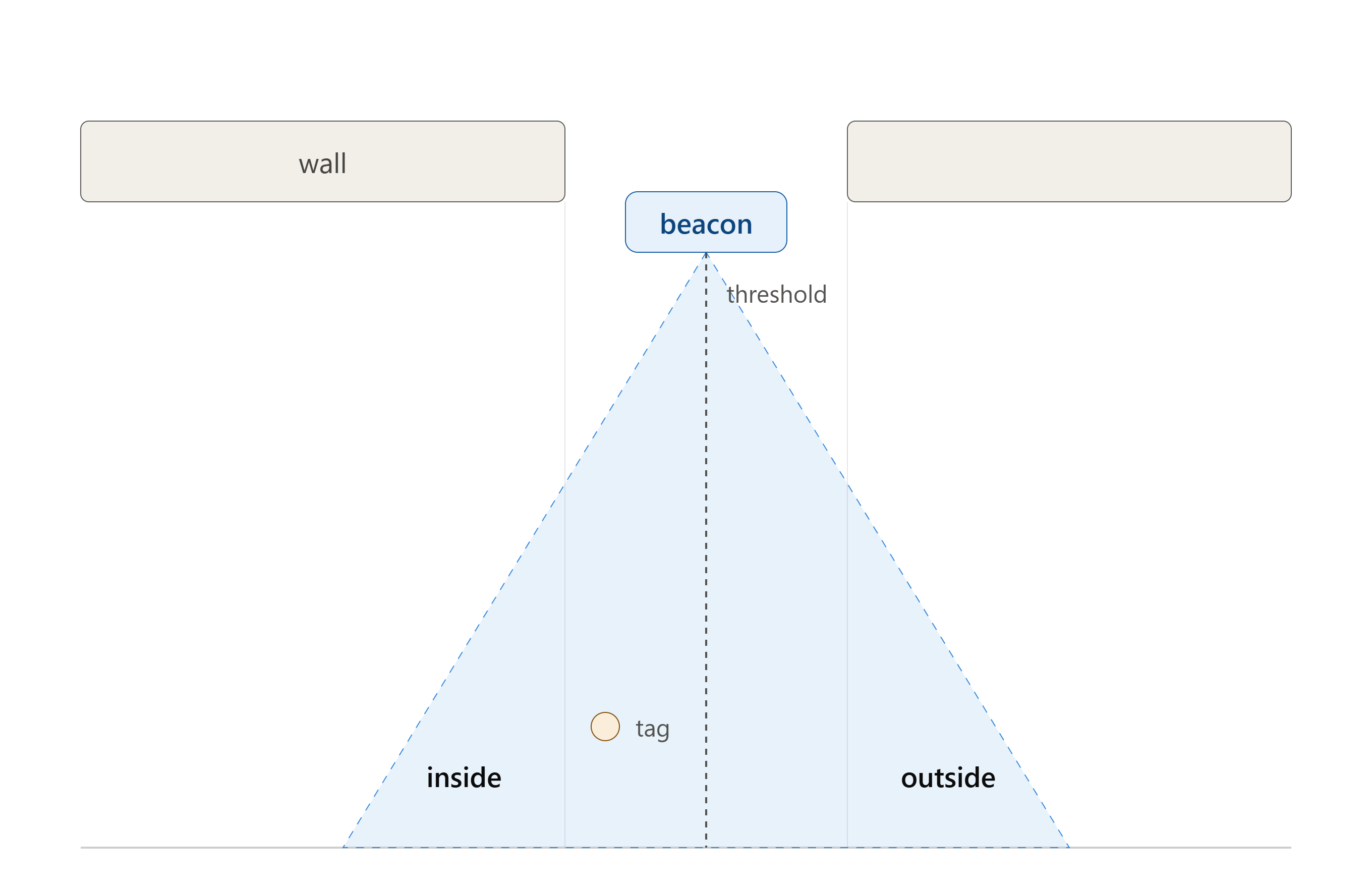
Sorry for the confusion. I actually use a bracket mounted to the wall right above the doorway, which lets me hold the board flat/horizontal, with the antennas pointing straight down toward the floor (same as a ceiling mount would achieve, just anchored to the wall instead of the ceiling). Reference image below:

Sounds like we’re already aligned on the ideal mounting approach for this; flat, antenna-face down, symmetric coverage on both sides of the threshold. Any other suggestions are appreciated.

Ok , got it. Now I don’t know, but assume across the antennas provide for more differentiation than above and below. Which way is the board turned on its mount, antenna parallel to the door space or perpendicular?

To clarify the mount orientation: the board is horizontal (antenna face down), and the two antennas’ baseline runs across the doorway. One antenna sits closer to the door/threshold side, the other sits closer to the inside-of-room side. So the phase-difference axis is aligned with the direction of travel through the doorway (perpendicular to the door plane), not parallel to it.

This orientation gives me the inside/outside sign convention in the first place (positive when the tag is on the room-side antenna’s side, negative on the door-side antenna’s side).

See the attached Murata board image for reference. I’ve labeled the antenna closer to the door as A and the one closer to the inside of the room as B (in red).

Great! We are talking about the same orientation.

Thanks rexxdad. Confirming this is the orientation I’ve been using throughout testing (antenna face down, baseline across the doorway, A closer to door / B closer to inside). Mounting/orientation is not the variable causing the sign flips.

I dug into Qorvo’s own APH511 (UWB AoA Antenna Fundamentals) app note, Section 5 Front-Back Ambiguity, which was added in the Nov 2024 rev 1.1 update. It states directly:

“With raw PDoA measurements, there can be ambiguity as to which side of the array the received pulse came from… The position of the Tx node can be symmetric around the x axis, thus y can be positive or negative and give the same phase difference.”

That matches exactly what I’m seeing in my logs. Same position, same distance, sign flipping with no change in the physical inside/outside state.

The doc’s suggested mitigation is:

“With directive antennas, the ambiguity may be resolved by the received signal strength where lower power is received from the back.”

That doesn’t apply to my setup. I need symmetric coverage on both sides of the doorway by design, so there’s no strong/weak lobe difference for RSSI to key off of, which lines up with what I’m already seeing (RSSI is clean and equal on both true and false readings).

So this looks like a known, documented limitation of 2-antenna PDoA arrays, not something fixable through mounting, calibration, or firmware on this hardware.

Still open questions from earlier in the thread if anyone has insight:

  1. Does the QM33120W’s time-multiplexed RX switching (vs. simultaneous dual-RX) introduce additional phase error during tag motion, on top of the base front-back ambiguity?
  2. Is there any CIR/multipath diagnostic on the QM33120W that flags an untrustworthy phase sample independent of RSSI?

Otherwise it sounds like a 3rd antenna (or different chip with a 3rd simultaneous RX chain) is the real fix here rather than anything on the current 2-antenna platform.
APH511_UWB_AoA_Antenna_Fundamentals.pdf (343.3 KB)

Do you get any kind of trend pattern including w rssi on first detection thru center and out?

What percentage of the readings are false?

I’ve not used the PDoA so can’t help there but I do have a question about the system design.

How accurate do you need the doorway threshold detection to be? While one sensor if clearly preferable would two simpler ones be acceptable?

I’ve done similar detection using TWR and two anchors, one each side of the door. If they are equal distance from the doorway then the shortest range gives you a simple indication of the side.
It’s not as elegant and requires more devices in the building but it is simple and since ranges are generally more accurate than angles can sometimes work better.

@rexxdad Good question. I don’t have a clean trend/percentage breakdown yet, just the sample log I posted. I’ll be running more structured tests soon (fixed positions, varying rotation/distance, near-threshold specifically) and will follow up with results.

@AndyA Appreciate the suggestion, but two-anchor TWR won’t work for this project. I need this to work as a single beacon per doorway. The threshold does not have to be perfect, I just need to be able to differentiate when the tag is inside vs outside consistently and reliably.

Will follow up with real data soon.

Hi, I have worked extensively with the Type 2AB dev board you are using, and I can tell you that the front/back ambiguity applies to the front and back of the dev board itself. In this case, since one side of your dev board is facing the ceiling, the ambiguity is already resolved as the signal cannot come from there.

I suspect the actual problem causing your measurement issues could be 2 things:

  • PDoA measurements tend to be rather noisy and prone to outliers. Try averaging over the last 10-50 measurements and see if the accuracy improves.
  • From my testing, the tag’s antenna also needs to be facing the anchor for the most accurate PDoA measurements. I noticed that when I rotate the tag’s antenna away from the anchor, the anchor’s PDoA measurements become very inaccurate. Because of this you might need a omnidirectional antenna for the tag.

Andy’s suggestion is also worth noting. Your application can be achieved with a much simpler TWR system with an anchor placed inside the room. Any distances below a certain threshold is indicative of the tag being inside the room. This would only require 1 anchor per room. Use the dual sided TWR example for the best accuracy (you might need to change the timing parameters for it to work on the 2AB) and increase preamble and STS length for better reception in non LOS environments. This system would be substantially simplier, cheaper, and more reliable compared to PDoA.

Thinking about this today, I would make to clasp for the wearable at the top where the antenna is(think pear shaped ) also the antenna are not on the body side