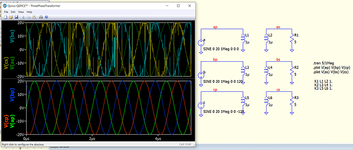
I’m beginning the process of building out a three phase transformer model, but ran into this issue. The simulation works well for two phases of coupled inductors, but when I add the third it breaks. Why is this happening, and how can I fix it?
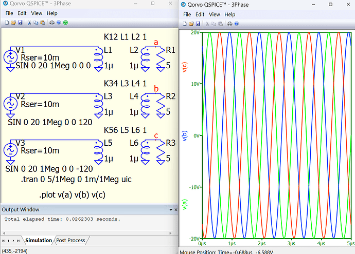
Thanks! Any reason why the series resistance is required at the source?
Because the total resistance of the voltage source and the primary winding equal to 0 is an error. Many Spice programs fix this, issue a warning and do not start the calculation.
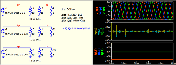
This weird secondary voltage profile can be replicated with only a single voltage source, as long as you set a non-zero phase angle and without series resistance. The problem is that, transient simulation begin with dc condition, and what the dc condition for phase-shifted voltage source in parallel to a inductor? That a huge dc current! (i.e. a finite voltage in parallel to a pure inductor, in theory the steady state current is infinite)
Therefore, if you monitor current of L1, L3 and L5, you can see L3 and L5 in TA level, where all crazy thing can happen in the calculation results.
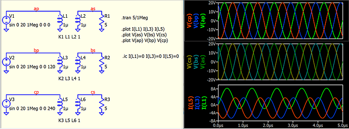
If you force initial condition for L1, L3 and L5 to zero, you will get the waveform back.
UIC in @bordodynov example will skip dc calculation and force start simulation with initial condition to 0A too.
Thank you both. That is very helpful for my understanding of how the simulator works.


