Hi All
Why would the circuit not output a square wave?
Regards
ike
Hi All
Why would the circuit not output a square wave?
Regards
ike
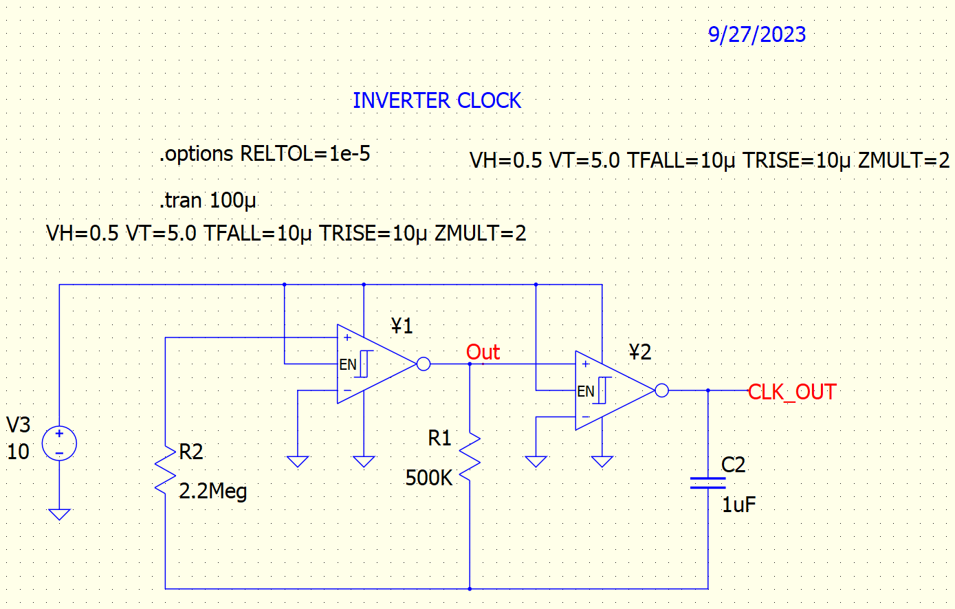
Hi
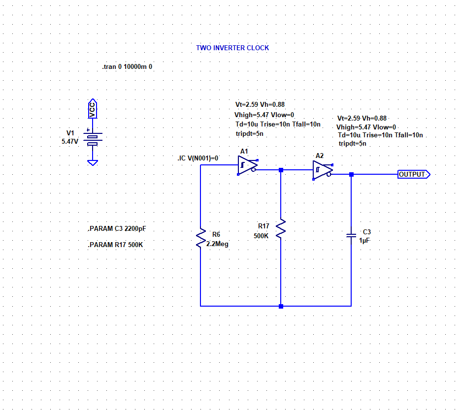
My schematic is as follows. Simulating a similar circuit using CD4000 series CMOS quad NAND CD4093 gates as inverters with hysteresis in LTSpice produces a nice square wave signal output but not this QSPICE circuit. Any clues would be of great help.
Regards
ike
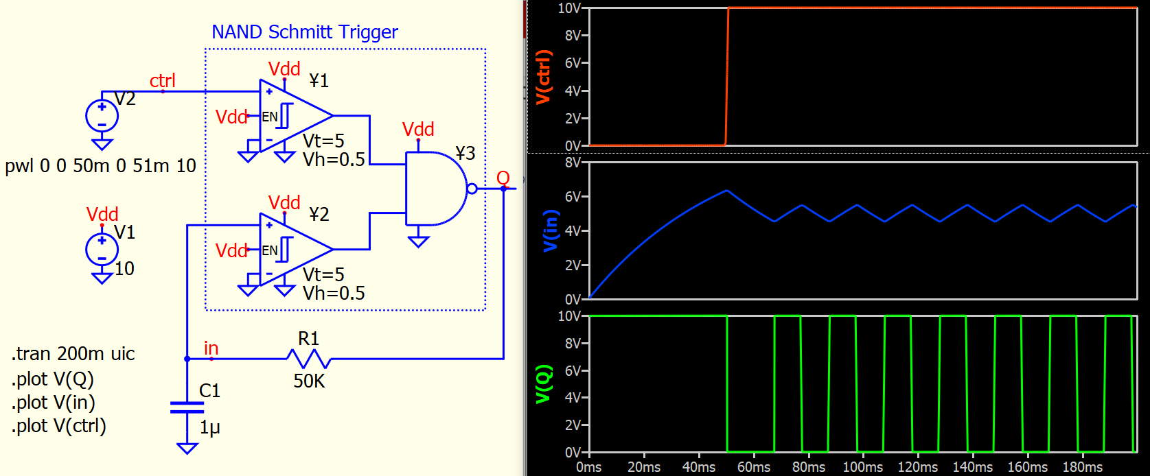
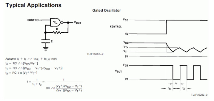
Not familiar with inverter clock, but a gated oscillator works well.
NAND Schmitt Trigger in this example is built with two schmitt trigger and a NAND gate.
Hi KSKelvin
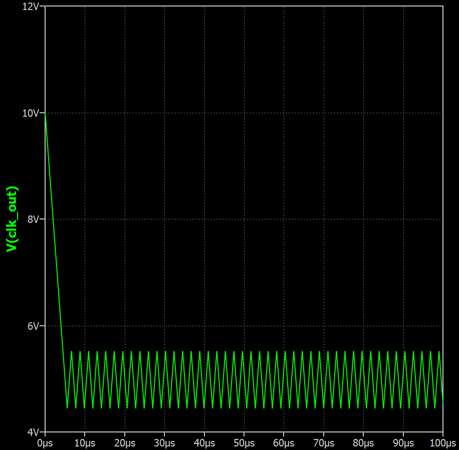
Thank you. I also expected the output of my circuit to be as square as yours at node ‘Q’ but instead it is triangular as shown at node ‘clk_out’. Not sure why?
Regards
ike
Hi KSKelvin
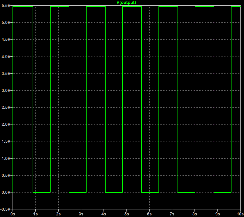
The two inverter clock appears below and its corresponding LTSpice simulated output observed at node ‘output’.
Regards
ike
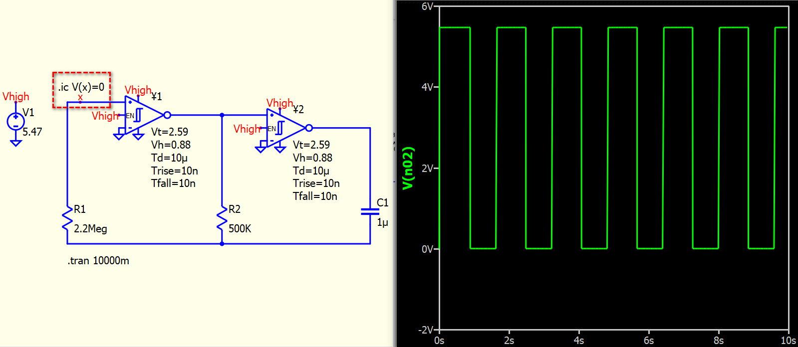
Your LTspice schematic has .ic V(N001)=0 to force A1 input to start at 0V in the simulation.
In Qspice, please use .ic to define an initial condition. I can yield the same result with initial condition added for your circuit.
Thank you. That may have been the missing link.
Regards
ike