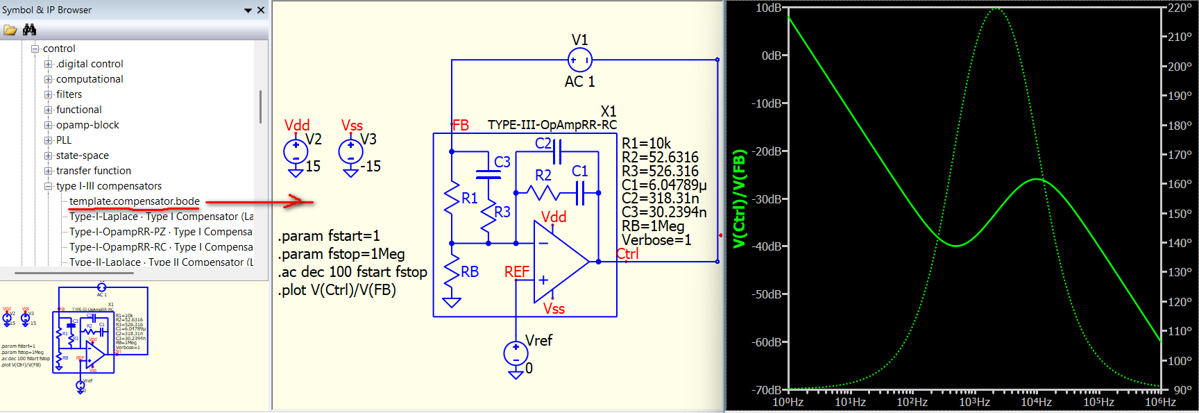
One more simple feature: I have a test template in the compensator symbol folder. You can just open a new schematic, drag it into the schematic, and run a Bode plot for the controller. You can delete the default controller and put any Type I, II, or III controller there, as I made sure the footprints of all six versions are the same. This allows you to quickly take a look at your Bode plot.

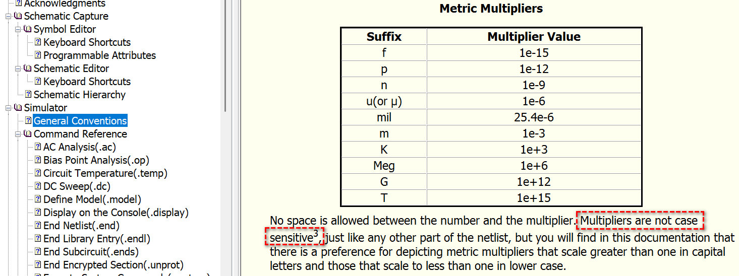
This is a limitation of .display, as confirmed with Mike Engelhardt. “M” or “m” represents 1e-3, and Meg represent 1e6. This is a SPICE tradition, as it is case-insensitive for metric multipliers.
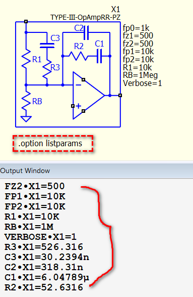
There is an alternative way to read subcircuit parameters, by adding .option listparams. This will give better metric multipliers. But if you have multiple subcircuits, you get all their parameters. That why I use .display.
1 Like
Awesome! The more I learn about QSpice, the more I like it. 

I have never heard of taking the Bode plot of only a compensator. What information do you obtain from ONLY plotting the compensator? Generally it is the open-loop L(s) that is plotted.
Can you please elaborate.
I mean Type I, II and III compensator in SMPS (not all kind of compensator and in all situation)… do you find any refer in designing their response not in frequency domain in SMPS application?
Of course, you put the compensator into the loop to plot frequency response, but sometime we also want to see the frequency only with the compensator. We have to know where to boost the phase, right?
But what does that have to do with plotting only the Bode plot of the controller? This is new to me.
This is a new concept tbh. I have never studied it this way.
Studying the compensator loop gain is very basic thing.
Demystifying Type II and Type III Compensators Using Op-Amp and OTA for DC/DC Co
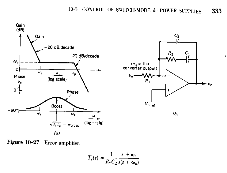
I learned that in my first power electronics course in undergrad… so, nowadays, do they teach something different? I just don’t quite understand how we can design a compensator without looking into its frequency domain response. Here was the textbook I used, p.335 in Power Electronics - Converters Applications and Design by Mohan.
Yeah, the way I learned it is that you plot the plant frequency response first and then you compensate it accordingly (i.e., do you apply a lead or lag compensator here, depending if you need to add phase or subtract phase, etc.)
I actually did not study power electronics. My major focus was in circuits and systems with an emphasis in RF. 
All of this is self taught. I started studying control theory on my own (Modern Control Systems, Dorf/Bishop - the whole book) and now am applying the theory to actual applications (currently to buck converters).
1 Like
Oh, I get that!!! You never take a power electronic course?
Nope. No power electronics courses. 
Then you are doing a very good job.
I had a weird feeling during our discussion, as it seemed you knew certain things very well, but something felt off when dealing with very basic power electronics concepts. Now I understand why.
Looking at the first version of your schematic, I assumed you came from a power electronics background, as you were able to set up the schematic quite well and also had a functional Type III compensator. (I guess even some people from a power electronics background may not be able to build a simulation up to that point.)
Welcome to power electronics! I went the opposite way—I started in power electronics and ended up in RF (but just in MHz range).
1 Like
Thank you.
Yes, well in addition to reading Dorf/Bishop, I have also been studying a few app notes here and there (and yes, a few from TI as well). I initially wanted to only design the compensator. But, now, currently getting more into the design aspect of buck converters to give me a better understanding on how best to approach the compensator design. Currently reading up on this app note:
SLVA301
Loop Stability Analysis of Voltage Mode Buck Regulator With Different Output Capacitor Types – Continuous and Discontinuous Modes
The app note before this one was App Note 1162 from International Rectifier.
So, yes, been getting more involved little by little.