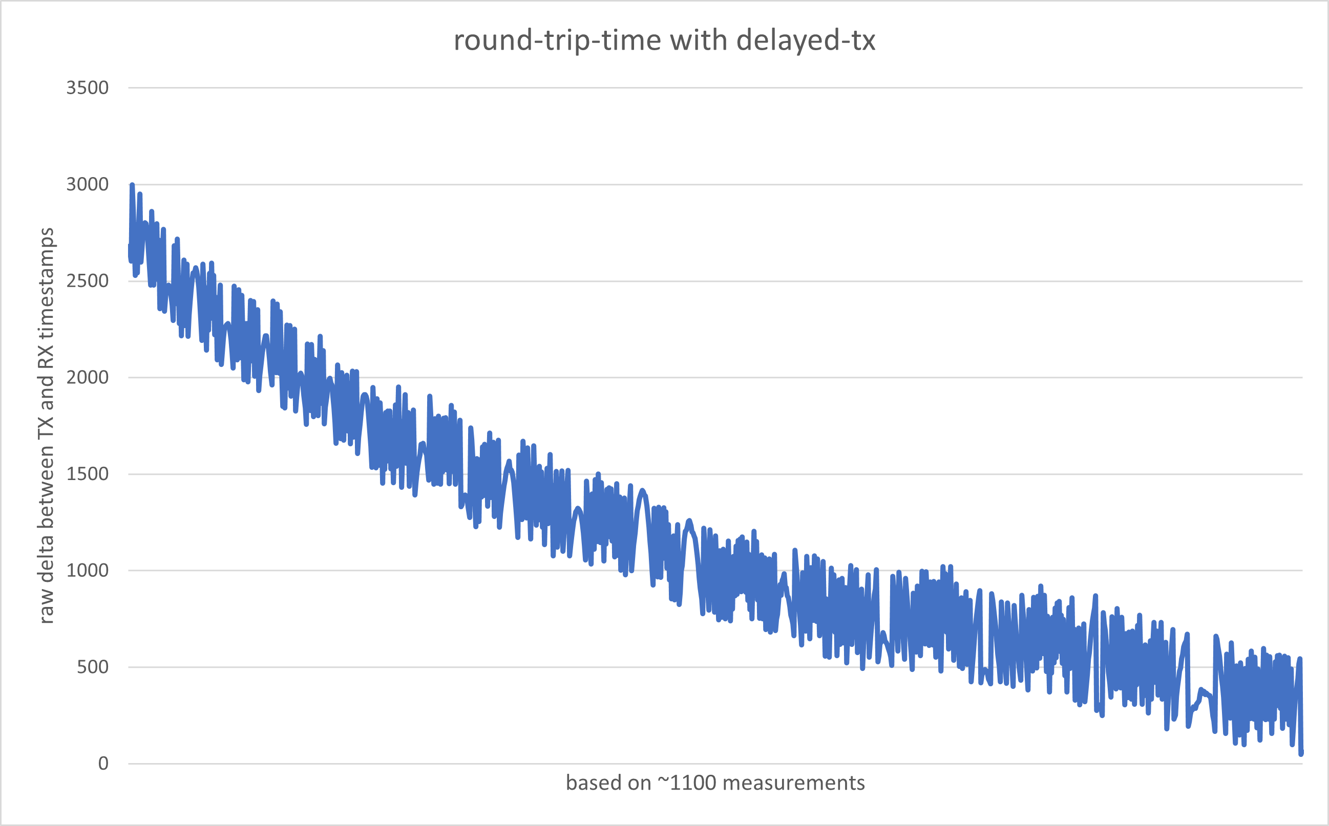
I’ve built a simple setup with two makerfabs DW3000 modules. One module sends an empty frame, the other receives the frame and initiates a delayed transfer back to module 1. I then read the TX and RX timestamps that got saved on module 1 to calculate the round-trip-times (reg 0x00:0x64 and 0x00:0x74) (rt=rx-tx).
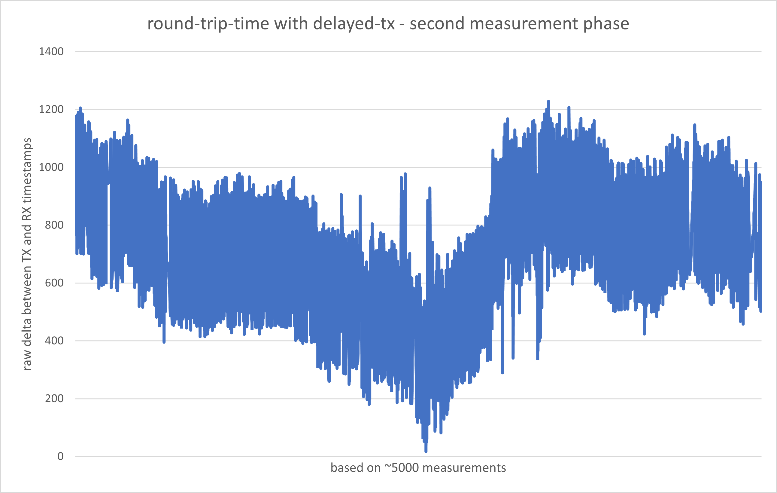
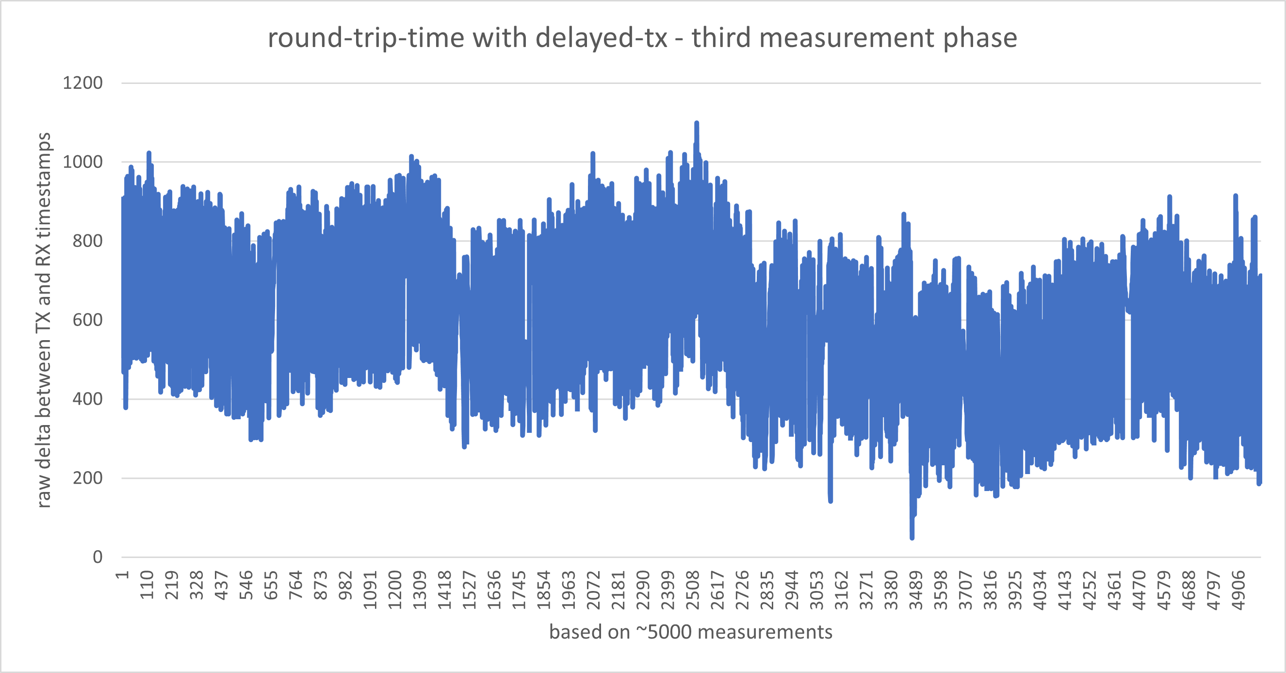
And these were right after the last one with also 5000 measurements.
Mean deviation 146
The thing that really bothers me is, that the results vary far too much between single measurements. The mean deviation on both graphs is way too high for any accurate distance measurements in my opinion.
When setting a delayed transmit time the 9 least significant bits of the timestamp are ignored. This will give 512 time units of variation in the delay, which looks to be about what you are seeing.
So if you receive a message with a 40 bit timestamp of 0x11 22 33 44 55 and then add a fixed delay of
0x01 23 45 time units you would expect the resulting transmission to be sent at 0x 11 22 34 67 9a
But in reality the message will be sent at 0x11 22 34 66 00
You need to include the error (0x19a in this case) as part of the message that is sent, that way the other end can add this on to the measured time to compensate for this.
That should get you to a far more consistent delay number.
In order to get an accurate and stable over time distance you also need to factor a few other things in.
The clocks on the two devices will be running at slightly different speeds so a fixed delay on one unit may be a slightly different length of time on another unit. Since the delay time is far longer than the actual message travel time even a tiny difference in clocks will be enough to have a huge impact on the range. There is a register you can read from the DW3000 to give you an estimate of the clock differences so that you can correct for this.
Also note that when doing a scheduled transmit that is the time that the chip starts the transmission, normally you want to specify the time when the signal leaves the antenna. This means you will normally want to subtract the antenna transmit delay time to the calculated time.
If I get it correctly, the 9 bits aren’t ignored in the DX_TIME register itself but rather after calculating the time when the frame should be send, right?
So I’d need to read the rx timestamp to the host, add the delay, zero the last 9 bits, calculate the difference and send the difference back inside the frame itself?
Do you have a reference for how long this process should take approximately? Currently I am writing a delay of 0xFFFFFE to the register.
Also, you mentioned here…
that the tx timestamp of the initiating transceiver is sent within the frame to transceiver 2. What use does this have, if both clocks run asynch anyways?
Currently, I just send an empty frame, receive it and use the CMD_DTX_RS fast command to send it back after the delayed with respect to the RX timestamp. After receiving the frame on transceiver 1, I’d subtract antenna delays, the delay and correct the clock drift.
Is there a favorible method over this one? It seemed like the simplest one
Looks like I was getting DW1000 and DW3000 mixed up, the DW1000 has a 40 bit tx time register where the low 9 are ignored. The DW3000 has a 32 bit register where only the low bit is ignored. The end result is the same, it just saves you setting the low byte when it’s ignored. The time resolution restriction is on the final Tx time, not any intermediate values. So if using CMD_DTX_RS it’s not on the register value directly but on the calculated time.
So the process is:
Read the Rx timestamp. Add the delay required. Subtract antenna Tx delay. That gives you the high resolution time for when you would want the signal to be transmitted.
And the calculated time with 0x1FF, include that result in your message data.
Right shift the calculated time by 8 bits and load the result into the DX_TIME register.
Load your message and send a CMD_DTX command
Do you have a reference for how long this process should take approximately? Currently I am writing a delay of 0xFFFFFE to the register.
It depends on your processor speed, SPI bus speed, packet length and radio settings.
As a minimum it must be the time taken to actually send a radio message plus your worst case processing time. Unless you have a very long packet or massive preamble then a delay of 2 ms should be safe. If you push everything to the absolute minimums then <300 us is possible (a minimum length packet is around 150 us over the air).
I am assuming things are either interrupt driven or polled at a high rate, obviously if polling at a low rate your worst case processing time could be a lot longer.
Sorry, wasn’t clear. By timestamp i ment the receive time that you get from the chip, not data included in the packet.
Yes, the method you give is the simplest way to do it. It’s a minimal a single sided two way range implementation.
One simple refinement you may want to add is to include initiator and responder IDs in both messages, that lets you handle multiple tags and anchors. And if you want to get sneaky you measure the clock differences at both ends and include the measured value in the reply. You can then average the two and get a slight improvement and also check they are roughly the same magnitude and opposite signs as a sanity check on the data.
I did some more programming and got pretty close results, however there are still some factors that are quite weird to me.
If we take your maximum delay time of 2ms as the delay time, this would accord to 2.000.000ns. If I divide this number by 4 (as the unit for DX_TIME is ~4ns) I get 500.000 or 0b111110100. This number has 9 bits. Shifting 8 of those bits to the right, one bit remains to be written into the DX_TIME register - but this bit gets ignored, according to the manual.
So for the chip the delay is still 0?? I mean, how should the chip even know about the delay if 8 of its lowest bits aren’t even written to the chip (due to the bitshift)?
For me currently, anything below 0xFFFFFFFF just triggers the HPDWARN bit, meaning that the process isn’t initiated fast enough, so it takes the chip a whole cycle to do the delayed transfer. This number just seems insanely high, especially if you take into account that this register part has the 4ns unit instead of the 15.65ps the timestamps have.
Some quick mental arithmetic:
2 ms in ns = 2 * 1000 * 1000
1000 ~= 1024 = 2^10
So 2 ms in ns ~= 2^1 * 2^10 * 2^10
That means the number will be roughly 1+10+10 = 21 bits long.
Divide by 4 = remove 2 bits.
Right shift 8 = remove 8 bits.
That gives us a number to load into the register that is around 11 bits long.
Rather than using the CMD_DTX_RS command I’d recommend using the CMD_DTX command and explicitly setting the Tx time rather than setting the time difference. It’s not significantly harder to do things that way and gives you more visibility of exactly when things are supposed to happen. Also after loading the commands you can read the current time from DW and check how much margin you had left.