Hi,
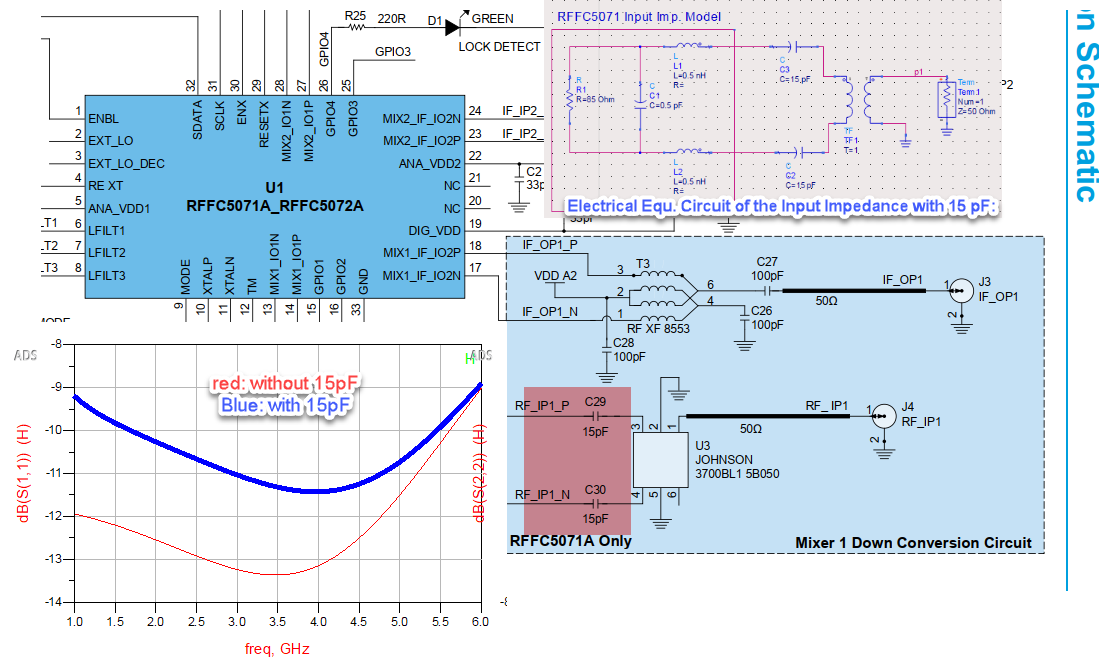
I have some questions regarding the input and output impedance of the RFFC5071A. In the datasheet section on impedance matching, the equivalent circuit model for the input impedance consists of an 85-ohm resistor, a 0.5pF shunt capacitor, and two 0.5nH series inductors.
In the recommended schematic for 3.7 GHz, two 15pF capacitors are used in series.
I simulated the recommended internal circuit using an ideal 1:1 transformer in ADS and compared its S11 with and without the 15pF series capacitor (as shown in the figure below). As you can see, adding the capacitor worsened the impedance matching instead of improving it.
Could you please check if there’s any mistake in my modeling or simulation? I’d like to ensure proper matching at other frequencies as well.
Thanks!