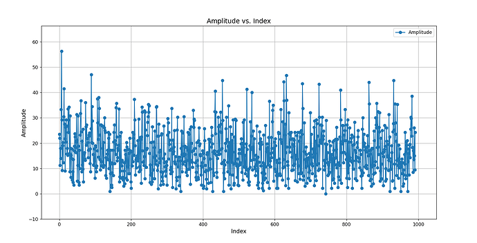
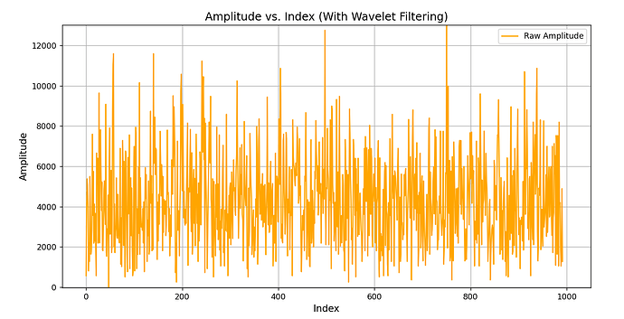
Hello! I’d like to ask about the sequence of reading CIR data for calculating why I cannot accurately capture the values at the First Path and Peak Path. My approach involves calculating the amplitude directly from the CIR values on the board. Afterward, I plot the graph using Python by reading the data from the board’s Serial Monitor. The graph looks like this
I chose to collect 3968 + 1 values (reserving one for the dummy byte) at PRF 16 MHz.
Here is the relevant part of the ESP32 code:
#include <SPI.h>
#include <DW1000Ranging.h>
#include <Wire.h>
#include <Adafruit_GFX.h>
#include <Adafruit_SSD1306.h>
#include <DW1000.h>
#include <DW1000Time.h>
// Device configuration
#define ANCHOR_ADD “11:11:11:11:11:11:11:11” // Anchor Address
#define TAG_ADD “12:12:12:12:12:12:12:12” // Tag Address
// Pin definitions
#define SPI_SCK 18
#define SPI_MISO 19
#define SPI_MOSI 23
#define UWB_RST 27
#define UWB_IRQ 34
#define UWB_SS 21
#define I2C_SDA 4
#define I2C_SCL 5
#define ACC_MEM_ADDRESS 0x25
#define ACCUMULATOR_SIZE (3968 + 1) // 3968 samples + 1 dummy byte
#define SPI_MAX_SPEED 115200
// Display initialization
Adafruit_SSD1306 display(128, 64, &Wire, -1);
SPISettings spiSettings(SPI_MAX_SPEED, MSBFIRST, SPI_MODE0);
// Global buffer for CIR data
uint8_t cirBuffer[ACCUMULATOR_SIZE];
void setup() {
Serial.begin(115200);
Wire.begin(I2C_SDA, I2C_SCL);
delay(1000);
// Initialize display
if (!display.begin(SSD1306_SWITCHCAPVCC, 0x3C)) {
    Serial.println(F("SSD1306 allocation failed"));
    while (true);
}
display.clearDisplay();
displayLogo();

// Initialize SPI and UWB
SPI.begin(SPI_SCK, SPI_MISO, SPI_MOSI);
DW1000Ranging.initCommunication(UWB_RST, UWB_SS, UWB_IRQ);

DW1000Ranging.attachNewRange(newRange);
DW1000Ranging.attachBlinkDevice(newBlink);
DW1000Ranging.attachInactiveDevice(inactiveDevice);

DW1000Ranging.startAsAnchor(ANCHOR_ADD, DW1000.MODE_SHORTDATA_FAST_LOWPOWER, false);
}
void loop() {
DW1000Ranging.loop();
}
// Callback for a new range event
void newRange() {
// Send start marker
for (int i = 0; i < 10; i++) {
Serial.write(0xFF);
}
// Calculate and send ToF
double tof_ns = calculateToF();
Serial.print("ToF (ns): ");
Serial.println(tof_ns, 4);

// Read CIR data
enableCIRClock();
readCIRData();
disableCIRClock();

// Send end marker
for (int i = 0; i < 10; i++) {
    Serial.write(0xFF);
}

delay(1000); // Optional delay
}
// Calculate time of flight (ToF)
double calculateToF() {
DW1000Time txTime, rxTime;
DW1000.getTransmitTimestamp(txTime);
DW1000.getReceiveTimestamp(rxTime);
uint64_t tof_units = rxTime.getTimestamp() - txTime.getTimestamp();
double tof_ns = (tof_units * (1.0 / 499.2e6) * 1e9) / 2; // Convert to nanoseconds
return tof_ns;
}
// Enable CIR clock
void enableCIRClock() {
uint8_t reg[2];
DW1000.readBytes(PMSC, PMSC_CTRL0_SUB, reg, 2);
reg[0] = 0x48 | (reg[0] & 0xb3);
reg[1] = 0x80 | reg[1];
DW1000.writeBytes(PMSC, PMSC_CTRL0_SUB, reg, 2);
}
// Disable CIR clock
void disableCIRClock() {
uint8_t reg[2];
DW1000.readBytes(PMSC, PMSC_CTRL0_SUB, reg, 2);
reg[0] &= 0xb3;
reg[1] &= 0x7f;
DW1000.writeBytes(PMSC, PMSC_CTRL0_SUB, reg, 2);
}
// Read CIR data and calculate amplitude
void readCIRData() {
const int sampleSize = 4; // 1 sample = 4 bytes (real + imag)
const uint16_t num_samples = (ACCUMULATOR_SIZE - 1) / sampleSize;
// Read raw CIR data
DW1000.readBytes(ACC_MEM_ADDRESS, 0, cirBuffer, ACCUMULATOR_SIZE);

for (uint16_t i = 0; i < num_samples; i++) {
    uint16_t offset = (i * sampleSize) + 1;

    // Convert to signed values
    int16_t real = (cirBuffer[offset + 1] << 8) | cirBuffer[offset];
    int16_t imag = (cirBuffer[offset + 3] << 8) | cirBuffer[offset + 2];

    // Compute amplitude using SQRT approximation
    int16_t abs_real = abs(real);
    int16_t abs_imag = abs(imag);
    float amplitude = max(abs_real, abs_imag) + 0.25 * min(abs_real, abs_imag);

    // Print amplitude for debugging
    Serial.print("Amplitude[");
    Serial.print(i);
    Serial.print("]: ");
    Serial.println(amplitude, 6);
}
}
// Display logo on OLED
void displayLogo() {
display.clearDisplay();
display.setTextSize(2);
display.setTextColor(SSD1306_WHITE);
display.setCursor(0, 0);
display.println(F(“Makerfabs”));
display.println(F(“UWB Anchor”));
display.setTextSize(1);
display.setCursor(0, 40);
display.println(ANCHOR_ADD);
display.display();
}
// Blink detection callback
void newBlink(DW1000Device *device) {
Serial.print("Blink from Tag detected! Device added → ");
Serial.print("Short Address: ");
Serial.println(device->getShortAddress(), HEX);
if (String(device->getShortAddress(), HEX) == TAG_ADD) {
    Serial.println("Tag connected successfully!");
}
}
// Inactive device callback
void inactiveDevice(DW1000Device *device) {
Serial.print("Delete inactive device: ");
Serial.println(device->getShortAddress(), HEX);
}
I would appreciate your advice on this. Thank you!

