Hi I am using two examples as double sided initiator and responder with interrupts but getting very high reading of distance.
This is my initiator side code
extern void test_run_info(unsigned char *data);

/* Default communication configuration. We use default non-STS DW mode. */
static dwt_config_t config = {
    9,
    DWT_PLEN_128,
    DWT_PAC8,
    9,
    9,
    1,
    DWT_BR_6M8,
    DWT_PHRMODE_STD,
    DWT_PHRRATE_STD,
    (129 + 8 - 8),
    DWT_STS_MODE_OFF,
    DWT_STS_LEN_64,
    DWT_PDOA_M0
};

/* Inter-ranging delay period, in milliseconds. */
#define RNG_DELAY_MS 1000

/* Default antenna delay values for 64 MHz PRF. See NOTE 1 below. */
#define TX_ANT_DLY 16385
#define RX_ANT_DLY 16385

/* Frames used in the ranging process. See NOTE 2 below. */
static uint8_t tx_poll_msg[] = { 0x41, 0x88, 0, 0xCA, 0xDE, 'W', 'A', 'V', 'E', 0x21 };
static uint8_t rx_resp_msg[] = { 0x41, 0x88, 0, 0xCA, 0xDE, 'V', 'E', 'W', 'A', 0x10, 0x02, 0, 0 };
static uint8_t tx_final_msg[] = { 0x41, 0x88, 0, 0xCA, 0xDE, 'W', 'A', 'V', 'E', 0x23, 0, 0, 0, 0, 0, 0, 0, 0, 0, 0, 0, 0 };
/* Length of the common part of the message (up to and including the function code, see NOTE 2 below). */
#define ALL_MSG_COMMON_LEN 10
/* Indexes to access some of the fields in the frames defined above. */
#define ALL_MSG_SN_IDX            2
#define FINAL_MSG_POLL_TX_TS_IDX  10
#define FINAL_MSG_RESP_RX_TS_IDX  14
#define FINAL_MSG_FINAL_TX_TS_IDX 18
/* Frame sequence number, incremented after each transmission. */
static uint8_t frame_seq_nb = 0;

/* Declaration of static functions. */
static void rx_ok_cb(const dwt_cb_data_t *cb_data);
static void rx_to_cb(const dwt_cb_data_t *cb_data);
static void rx_err_cb(const dwt_cb_data_t *cb_data);
static void tx_conf_cb(const dwt_cb_data_t *cb_data);
static void create_timers();

//variables for application timer
uint32_t msTicks     = 0;
uint32_t returnCode  = 0;
ret_code_t err_code;
APP_TIMER_DEF(m_repeated_timer_id);     /**< Handler for repeated timer. */

//User leds
#define  gpio_led_10  5
#define  gpio_led_11  22

//Event for dw3000 communication
#define timeout_event       1
#define reciever_event      2
#define transmit_event      3
#define error_event         4
#define led_control         5


uint8_t states = 10;
uint8_t ex_flag;


/* Hold copy of status register state here for reference so that it can be examined at a debug breakpoint. */
static uint32_t status_reg = 0;


#define POLL_TX_TO_RESP_RX_DLY_UUS (300 + CPU_PROCESSING_TIME)

#define RESP_RX_TO_FINAL_TX_DLY_UUS (300 + CPU_PROCESSING_TIME)

#define RESP_RX_TIMEOUT_UUS 300

#define PRE_TIMEOUT 5

#define TX_TO_RX_DELAY_UUS 60

#define RX_RESP_TO_UUS 5000

/* Default inter-frame delay period, in milliseconds. */
#define DFLT_TX_DELAY_MS 1000
/* Inter-frame delay period in case of RX timeout, in milliseconds.
 * In case of RX timeout, assume the receiver is not present and lower the rate of blink transmission. */
#define RX_TO_TX_DELAY_MS 3000
/* Inter-frame delay period in case of RX error, in milliseconds.
 * In case of RX error, assume the receiver is present but its response has not been received for any reason and retry blink transmission immediately. */
#define RX_ERR_TX_DELAY_MS 0
/* Current inter-frame delay period.
 * This global static variable is also used as the mechanism to signal events to the background main loop from the interrupt handler callbacks,
 * which set it to positive delay values. */
static int32_t tx_delay_ms = -1;
/* Buffer to store received frame. See NOTE 5 below. */
static uint8_t rx_buffer[FRAME_LEN_MAX];


/* Time-stamps of frames transmission/reception, expressed in device time units. */
static uint64_t poll_tx_ts;
static uint64_t resp_rx_ts;
static uint64_t final_tx_ts;

/* Values for the PG_DELAY and TX_POWER registers reflect the bandwidth and power of the spectrum at the current
 * temperature. These values can be calibrated prior to taking reference measurements. See NOTE 8 below. */
extern dwt_txconfig_t txconfig_options;

/*! ------------------------------------------------------------------------------------------------------------------
 * @fn dds_twr_initiator_interrupt()
 *
 * @brief Application entry point.
 *
 * @param  none
 *
 * @return none
 */
int dds_twr_initiator_interrupt(void)
{
    /* Display application name on LCD. */
    test_run_info((unsigned char *)APP_NAME);

    //Initialize application timer
    app_timer_init();
    //Create Timer instance
    create_timers();

    // Configure LED 10  --> P0.05 and LED 11 --> P0.22 as outputs
    nrf_gpio_cfg_output(gpio_led_10);
    nrf_gpio_cfg_output(gpio_led_11);


    /* Configure SPI rate, DW3000 supports up to 36 MHz */
    port_set_dw_ic_spi_fastrate();

    /* Reset DW IC */
    reset_DWIC(); /* Target specific drive of RSTn line into DW IC low for a period. */

    Sleep(2); // Time needed for DW3000 to start up (transition from INIT_RC to IDLE_RC

    /* Probe for the correct device driver. */
    dwt_probe((struct dwt_probe_s *)&dw3000_probe_interf);

    while (!dwt_checkidlerc()) /* Need to make sure DW IC is in IDLE_RC before proceeding */ { };

    if (dwt_initialise(DWT_DW_INIT) == DWT_ERROR)
    {
        test_run_info((unsigned char *)"INIT FAILED     ");
        while (1) { };
    }

    /* Configure DW IC. See NOTE 2 below. */
    /* if the dwt_configure returns DWT_ERROR either the PLL or RX calibration has failed the host should reset the device */
    if (dwt_configure(&config))
    {
        test_run_info((unsigned char *)"CONFIG FAILED     ");
        while (1) { };
    }

    /* Configure the TX spectrum parameters (power, PG delay and PG count) */
    dwt_configuretxrf(&txconfig_options);

    /* Register the call-backs (SPI CRC error callback is not used). */
    dwt_setcallbacks(&tx_conf_cb, &rx_ok_cb, NULL, &rx_err_cb, NULL, NULL, NULL);
//| DWT_INT_RXFTO_BIT_MASK
    /* Enable wanted interrupts (TX confirmation, RX good frames, RX timeouts and RX errors). */
    dwt_setinterrupt(DWT_INT_TXFRS_BIT_MASK | DWT_INT_RXFCG_BIT_MASK  | DWT_INT_RXPTO_BIT_MASK | DWT_INT_RXPHE_BIT_MASK
                         | DWT_INT_RXFCE_BIT_MASK | DWT_INT_RXFSL_BIT_MASK | DWT_INT_RXSTO_BIT_MASK,
        0, DWT_ENABLE_INT);

    /*Clearing the SPI ready interrupt*/
    dwt_writesysstatuslo(DWT_INT_RCINIT_BIT_MASK | DWT_INT_SPIRDY_BIT_MASK);

    /* Install DW IC IRQ handler. */
    port_set_dwic_isr(dwt_isr);

    //dwt_setpreambledetecttimeout(PRE_TIMEOUT);

    /* Apply default antenna delay value. See NOTE 1 below. */
    dwt_setrxantennadelay(RX_ANT_DLY);
    dwt_settxantennadelay(TX_ANT_DLY);

    /* Next can enable TX/RX states output on GPIOs 5 and 6 to help debug, and also TX/RX LEDs
     * Note, in real low power applications the LEDs should not be used. */
    dwt_setlnapamode(DWT_LNA_ENABLE | DWT_PA_ENABLE);

    ex_flag = 0;

    /* Loop forever initiating ranging exchanges. */
    while (1)
    {

      if(!ex_flag)
      {
          dwt_setpreambledetecttimeout(0);
          /* Write frame data to DW IC and prepare transmission. See NOTE 9 below. */
          tx_poll_msg[ALL_MSG_SN_IDX] = frame_seq_nb;
          dwt_writetxdata(sizeof(tx_poll_msg), tx_poll_msg, 0);  /* Zero offset in TX buffer. */
          dwt_writetxfctrl(sizeof(tx_poll_msg) + FCS_LEN, 0, 1); /* Zero offset in TX buffer, ranging. */

          /* Start transmission, indicating that a response is expected so that reception is enabled automatically after the frame is sent and the delay
           * set by dwt_setrxaftertxdelay() has elapsed. */
          dwt_starttx(DWT_START_TX_IMMEDIATE | DWT_RESPONSE_EXPECTED);
          //reset ticks value and start the timer
          msTicks = 0;
          err_code = app_timer_start(m_repeated_timer_id, APP_TIMER_TICKS(1), NULL);
          APP_ERROR_CHECK(err_code);
          ex_flag = 1;
      }

         switch(states)
         {

            case timeout_event  :
                 //Re-enable Reciever
                 if(ex_flag == 1)
                 {

                    //reset ticks value and stop the timer
                    msTicks = 0;
                    err_code = app_timer_stop(m_repeated_timer_id);
                    APP_ERROR_CHECK(err_code);

                    __disable_irq();


                    dwt_setpreambledetecttimeout(0);
                    /* Write frame data to DW IC and prepare transmission */
                    tx_poll_msg[ALL_MSG_SN_IDX] = frame_seq_nb;
                    dwt_writetxdata(sizeof(tx_poll_msg), tx_poll_msg, 0);  /* Zero offset in TX buffer. */
                    dwt_writetxfctrl(sizeof(tx_poll_msg) + FCS_LEN, 0, 1); /* Zero offset in TX buffer, ranging. */

                    /* Start transmission, indicating that a response is expected so that reception is enabled automatically after the frame is sent and the delay
                     * set by dwt_setrxaftertxdelay() has elapsed. */
                    dwt_starttx(DWT_START_TX_IMMEDIATE | DWT_RESPONSE_EXPECTED);


                    __enable_irq();


                    //reset ticks value and start the timer
                    msTicks = 0;
                    err_code = app_timer_start(m_repeated_timer_id, APP_TIMER_TICKS(1), NULL);
                    APP_ERROR_CHECK(err_code);
                    ex_flag = 1;

                 }
                 states = 10;

                 break;
            case reciever_event :

                /* Check that the frame is recieved from "DS TWR initiator with interrupt side".
                * As the sequence number field of the frame is not relevant, it is cleared to simplify the validation of the frame. */
                rx_buffer[ALL_MSG_SN_IDX] = 0;
                if (memcmp(rx_buffer, rx_resp_msg, ALL_MSG_COMMON_LEN) == 0)
                {

                    uint32_t final_tx_time;
                    int ret;

                    /* Retrieve poll transmission and response reception timestamp. */
                    poll_tx_ts = get_tx_timestamp_u64();
                    resp_rx_ts = get_rx_timestamp_u64();


                    //reset ticks value and stop the timer
                    ex_flag = 0;
                    msTicks = 0;
                    err_code = app_timer_stop(m_repeated_timer_id);
                    APP_ERROR_CHECK(err_code);


                    /* Compute final message transmission time. See NOTE 11 below. */
                    final_tx_time = (resp_rx_ts + (RESP_RX_TO_FINAL_TX_DLY_UUS * UUS_TO_DWT_TIME)) >> 8;
                    dwt_setdelayedtrxtime(final_tx_time);

                    /* Final TX timestamp is the transmission time we programmed plus the TX antenna delay. */
                    final_tx_ts = (((uint64_t)(final_tx_time & 0xFFFFFFFEUL)) << 8) + TX_ANT_DLY;

                    /* Write all timestamps in the final message. See NOTE 12 below. */
                    final_msg_set_ts(&tx_final_msg[FINAL_MSG_POLL_TX_TS_IDX], poll_tx_ts);
                    final_msg_set_ts(&tx_final_msg[FINAL_MSG_RESP_RX_TS_IDX], resp_rx_ts);
                    final_msg_set_ts(&tx_final_msg[FINAL_MSG_FINAL_TX_TS_IDX], final_tx_ts);

                    /* Write and send final message. See NOTE 9 below. */
                    tx_final_msg[ALL_MSG_SN_IDX] = frame_seq_nb;
                    dwt_writetxdata(sizeof(tx_final_msg), tx_final_msg, 0); /* Zero offset in TX buffer. */
                    dwt_writetxfctrl(sizeof(tx_final_msg) + FCS_LEN, 0, 1); /* Zero offset in TX buffer, ranging bit set. */
                    ret = dwt_starttx(DWT_START_TX_IMMEDIATE);
                    /* If dwt_starttx() returns an error, abandon this ranging exchange and proceed to the next one. See NOTE 13 below. */
                    if (ret == DWT_SUCCESS)
                    {
                        /* Clear TXFRS event. */
                        //dwt_writesysstatuslo(DWT_INT_TXFRS_BIT_MASK);

                        /* Increment frame sequence number after transmission of the final message (modulo 256). */
                        frame_seq_nb++;
                    }
                }

                 states = 10;
                 break;
            case transmit_event :
                 break;
            case error_event    :
                 /* Clear RX error/timeout events in the DW IC status register. */
                 dwt_writesysstatuslo(SYS_STATUS_ALL_RX_TO | SYS_STATUS_ALL_RX_ERR);
                 ex_flag = 0;
                 states = 10;
                 break;

            default :
                break;
         }

        /* Execute a delay between ranging exchanges. */
        if(!ex_flag) Sleep(RNG_DELAY_MS);
    }
}


/*! ------------------------------------------------------------------------------------------------------------------
 * @fn rx_ok_cb()
 *
 * @brief Callback to process RX good frame events
 *
 * @param  cb_data  callback data
 *
 * @return  none
 */
static void rx_ok_cb(const dwt_cb_data_t *cb_data)
{
    int i;

    /* Clear local RX buffer to avoid having leftovers from previous receptions. This is not necessary but is included here to aid reading the RX
     * buffer. */
    for (i = 0; i < FRAME_LEN_MAX; i++)
    {
        rx_buffer[i] = 0;
    }

    /* A frame has been received, copy it to our local buffer. */
    if (cb_data->datalength <= FRAME_LEN_MAX)
    {
        dwt_readrxdata(rx_buffer, cb_data->datalength, 0);
    }
    states = 2;
}
/*! ------------------------------------------------------------------------------------------------------------------
 * @fn rx_err_cb()
 *
 * @brief Callback to process RX error events
 *
 * @param  cb_data  callback data
 *
 * @return  none
 */
static void rx_err_cb(const dwt_cb_data_t *cb_data)
{
    (void)cb_data;

    /* TESTING BREAKPOINT LOCATION #3 */
}


 /**@brief Timeout handler for the repeated timer.
 */
static void repeated_timer_handler(void * p_context)
{
  //Time out condition
  if(++msTicks == 5000)
   {
      nrf_gpio_pin_toggle(gpio_led_10);
      states = 1;
      msTicks = 0;
   }
}

/**@brief Create timers.
 */
static void create_timers()
{

    // Create timers
    err_code = app_timer_create(&m_repeated_timer_id,
                                APP_TIMER_MODE_REPEATED,
                                repeated_timer_handler);
    APP_ERROR_CHECK(err_code);
}
And this this responder side code
extern void test_run_info(unsigned char *data);

/* Example application name */
#define APP_NAME "DS TWR RESP v1.0"

/* Default communication configuration. We use default non-STS DW mode. */
static dwt_config_t config = {
    9,                /* Channel number. */
    DWT_PLEN_128,     /* Preamble length. Used in TX only. */
    DWT_PAC8,         /* Preamble acquisition chunk size. Used in RX only. */
    9,                /* TX preamble code. Used in TX only. */
    9,                /* RX preamble code. Used in RX only. */
    1,                /* 0 to use standard 8 symbol SFD, 1 to use non-standard 8 symbol, 2 for non-standard 16 symbol SFD and 3 for 4z 8 symbol SDF type */
    DWT_BR_6M8,       /* Data rate. */
    DWT_PHRMODE_STD,  /* PHY header mode. */
    DWT_PHRRATE_STD,  /* PHY header rate. */
    (129 + 8 - 8),    /* SFD timeout (preamble length + 1 + SFD length - PAC size). Used in RX only. */
    DWT_STS_MODE_OFF, /* STS disabled */
    DWT_STS_LEN_64,   /* STS length see allowed values in Enum dwt_sts_lengths_e */
    DWT_PDOA_M0       /* PDOA mode off */
};

/* Inter-ranging delay period, in milliseconds. */
#define RNG_DELAY_MS 1000

/* Default antenna delay values for 64 MHz PRF. See NOTE 1 below. */
#define TX_ANT_DLY 16385
#define RX_ANT_DLY 16385

/* Frames used in the ranging process. See NOTE 2 below. */
static uint8_t rx_poll_msg[] = { 0x41, 0x88, 0, 0xCA, 0xDE, 'W', 'A', 'V', 'E', 0x21, 0, 0 };
static uint8_t tx_resp_msg[] = { 0x41, 0x88, 0, 0xCA, 0xDE, 'V', 'E', 'W', 'A', 0x10, 0x02, 0, 0, 0, 0 };
static uint8_t rx_final_msg[] = { 0x41, 0x88, 0, 0xCA, 0xDE, 'W', 'A', 'V', 'E', 0x23, 0, 0, 0, 0, 0, 0, 0, 0, 0, 0, 0, 0, 0, 0 };
/* Length of the common part of the message (up to and including the function code, see NOTE 2 below). */
#define ALL_MSG_COMMON_LEN 10
/* Index to access some of the fields in the frames involved in the process. */
#define ALL_MSG_SN_IDX            2
#define FINAL_MSG_POLL_TX_TS_IDX  10
#define FINAL_MSG_RESP_RX_TS_IDX  14
#define FINAL_MSG_FINAL_TX_TS_IDX 18
/* Frame sequence number, incremented after each transmission. */
static uint8_t frame_seq_nb = 0;

/* Declaration of static functions. */
static void rx_ok_cb(const dwt_cb_data_t *cb_data);
static void rx_to_cb(const dwt_cb_data_t *cb_data);
static void rx_err_cb(const dwt_cb_data_t *cb_data);
static void tx_conf_cb(const dwt_cb_data_t *cb_data);
static void create_timers();

//variables for application timer
uint32_t msTicks     = 0;
uint32_t returnCode  = 0;
ret_code_t err_code;
APP_TIMER_DEF(m_repeated_timer_id);     /**< Handler for repeated timer. */

//User leds
#define  gpio_led_10  5
#define  gpio_led_11  22

//Event for dw3000 communication
#define timeout_event       1
#define reciever_event      2
#define transmit_event      3
#define error_event         4
#define led_control         5


uint8_t states = 10;
uint8_t ex_flag;
uint8_t tx_flag = 0;

/* Hold copy of status register state here for reference so that it can be examined at a debug breakpoint. */
static uint32_t status_reg = 0;

/* Delay between frames, in UWB microseconds. See NOTE 4 below. */
/* This is the delay from Frame RX timestamp to TX reply timestamp used for calculating/setting the DW IC's delayed TX function. This includes the
 * frame length of approximately 190 us with above configuration. */
#define POLL_RX_TO_RESP_TX_DLY_UUS  900
/* This is the delay from the end of the frame transmission to the enable of the receiver, as programmed for the DW IC's wait for response feature. */
#define RESP_TX_TO_FINAL_RX_DLY_UUS 500
/* Receive final timeout. See NOTE 5 below. */
#define FINAL_RX_TIMEOUT_UUS        220
/* Preamble timeout, in multiple of PAC size. See NOTE 6 below. */
#define PRE_TIMEOUT 5


/* Delay from end of transmission to activation of reception, expressed in UWB microseconds (1 uus is 512/499.2 microseconds). See NOTE 3 below. */
#define TX_TO_RX_DELAY_UUS 60

/* Receive response timeout, expressed in UWB microseconds. See NOTE 4 below. */
#define RX_RESP_TO_UUS     5000

/* Default inter-frame delay period, in milliseconds. */
#define DFLT_TX_DELAY_MS   1000
/* Inter-frame delay period in case of RX timeout, in milliseconds.
 * In case of RX timeout, assume the receiver is not present and lower the rate of blink transmission. */
#define RX_TO_TX_DELAY_MS  3000


/* Buffer to store received frame. See NOTE 5 below. */
static uint8_t rx_buffer[FRAME_LEN_MAX];


/* Timestamps of frames transmission/reception. */
static uint64_t poll_rx_ts;
static uint64_t resp_tx_ts;
static uint64_t final_rx_ts;


static double tof;
static double distance;

extern dwt_txconfig_t txconfig_options;

/*! ------------------------------------------------------------------------------------------------------------------
 * @fn ds_twr_responder_interrupt()
 *
 * @brief Application entry point.
 *
 * @param  none
 *
 * @return none
 */
int ds_twr_responder_interrupt(void)
{
    /* Display application name on LCD. */
    test_run_info((unsigned char *)APP_NAME);

    //Initialize application timer
    app_timer_init();
    //Create Timer instance
    create_timers();

    // Configure LED 10  --> P0.05 and LED 11 --> P0.22 as outputs
    nrf_gpio_cfg_output(gpio_led_10);
    nrf_gpio_cfg_output(gpio_led_11);

    /* Configure SPI rate, DW3000 supports up to 36 MHz */
    port_set_dw_ic_spi_fastrate();

    /* Reset DW IC */
    reset_DWIC(); /* Target specific drive of RSTn line into DW IC low for a period. */

    Sleep(2); // Time needed for DW3000 to start up (transition from INIT_RC to IDLE_RC

    /* Probe for the correct device driver. */
    dwt_probe((struct dwt_probe_s *)&dw3000_probe_interf);

    while (!dwt_checkidlerc()) /* Need to make sure DW IC is in IDLE_RC before proceeding */ { };

    if (dwt_initialise(DWT_DW_INIT) == DWT_ERROR)
      {
          test_run_info((unsigned char *)"INIT FAILED     ");
          while (1) { };
      }

    /* Configure DW IC. See NOTE 15 below. */
    /* if the dwt_configure returns DWT_ERROR either the PLL or RX calibration has failed the host should reset the device */
    if (dwt_configure(&config))
      {
          test_run_info((unsigned char *)"CONFIG FAILED     ");
          while (1) { };
      }

    /* Configure the TX spectrum parameters (power, PG delay and PG count) */
    dwt_configuretxrf(&txconfig_options);

    /* Register the call-backs (SPI CRC error callback is not used). */
    dwt_setcallbacks(&tx_conf_cb, &rx_ok_cb, NULL, &rx_err_cb, NULL, NULL, NULL);
// | DWT_INT_RXFTO_BIT_MASK
    /* Enable wanted interrupts (TX confirmation, RX good frames, RX timeouts and RX errors). */
    dwt_setinterrupt(DWT_INT_TXFRS_BIT_MASK | DWT_INT_RXFCG_BIT_MASK| DWT_INT_RXPTO_BIT_MASK | DWT_INT_RXPHE_BIT_MASK
                         | DWT_INT_RXFCE_BIT_MASK | DWT_INT_RXFSL_BIT_MASK | DWT_INT_RXSTO_BIT_MASK,
        0, DWT_ENABLE_INT);

    /*Clearing the SPI ready interrupt*/
    dwt_writesysstatuslo(DWT_INT_RCINIT_BIT_MASK | DWT_INT_SPIRDY_BIT_MASK);

    /* Install DW IC IRQ handler. */
    port_set_dwic_isr(dwt_isr);

    /* Apply default antenna delay value. See NOTE 1 below. */
    dwt_setrxantennadelay(RX_ANT_DLY);
    dwt_settxantennadelay(TX_ANT_DLY);

    /* Next can enable TX/RX states output on GPIOs 5 and 6 to help debug, and also TX/RX LEDs
     * Note, in real low power applications the LEDs should not be used. */
    dwt_setlnapamode(DWT_LNA_ENABLE | DWT_PA_ENABLE);


    ex_flag = 0;

    /* Loop forever responding to ranging requests. */
    while (1)
    {

    if(!ex_flag)
    {
        dwt_setpreambledetecttimeout(0);
        /* Activate reception immediately. */
        dwt_rxenable(DWT_START_RX_IMMEDIATE);
        //reset ticks value and start the timer
        msTicks = 0;
        err_code = app_timer_start(m_repeated_timer_id, APP_TIMER_TICKS(1), NULL);
        APP_ERROR_CHECK(err_code);
        ex_flag = 3;
    }

         switch(states)
         {

            case timeout_event  :
                 //Re-enable Reciever
                 if(ex_flag == 0)
                 {
                    dwt_setpreambledetecttimeout(0);
                    dwt_rxenable(DWT_START_RX_IMMEDIATE);
                 }

                 else if(ex_flag == 3)
                 {
                    //reset ticks value and stop the timer
                    msTicks = 0;
                    err_code = app_timer_stop(m_repeated_timer_id);
                    APP_ERROR_CHECK(err_code);

                   __disable_irq();


                    dwt_setpreambledetecttimeout(0);
                    dwt_rxenable(DWT_START_RX_IMMEDIATE);

                    __enable_irq();

                    //reset ticks value and start the timer
                    msTicks = 0;
                    err_code = app_timer_start(m_repeated_timer_id, APP_TIMER_TICKS(1), NULL);
                    APP_ERROR_CHECK(err_code);
                    ex_flag = 3;
                 }

                 states = 10;

                 break;
            case reciever_event :

                /* Check that the frame is recieved from "DS TWR initiator with interrupt side".
                * As the sequence number field of the frame is not relevant, it is cleared to simplify the validation of the frame. */
                rx_buffer[ALL_MSG_SN_IDX] = 0;
                if (memcmp(rx_buffer, rx_poll_msg, ALL_MSG_COMMON_LEN) == 0)
                {

                    uint32_t resp_tx_time;
                    int ret;

                    /* Retrieve poll reception timestamp. */
                    poll_rx_ts = get_rx_timestamp_u64();


                    //reset ticks value and stop the timer
                    msTicks = 0;
                    err_code = app_timer_stop(m_repeated_timer_id);
                    APP_ERROR_CHECK(err_code);

                    /* Set send time for response. See NOTE 9 below. */
                    resp_tx_time = (poll_rx_ts + (POLL_RX_TO_RESP_TX_DLY_UUS * UUS_TO_DWT_TIME)) >> 8;
                    dwt_setdelayedtrxtime(resp_tx_time);

                    /* Set expected delay and timeout for final message reception. See NOTE 4 and 5 below. */
                    dwt_setrxaftertxdelay(RESP_TX_TO_FINAL_RX_DLY_UUS);
                    //dwt_setrxtimeout(FINAL_RX_TIMEOUT_UUS);
                    /* Set preamble timeout for expected frames. See NOTE 6 below. */
                    dwt_setpreambledetecttimeout(PRE_TIMEOUT);

                    /* Write and send the response message. See NOTE 10 below.*/
                    tx_resp_msg[ALL_MSG_SN_IDX] = frame_seq_nb;
                    dwt_writetxdata(sizeof(tx_resp_msg), tx_resp_msg, 0); /* Zero offset in TX buffer. */
                    dwt_writetxfctrl(sizeof(tx_resp_msg), 0, 1);          /* Zero offset in TX buffer, ranging. */
                    tx_flag = 0;
                    ret = dwt_starttx(DWT_START_TX_IMMEDIATE | DWT_RESPONSE_EXPECTED);

                    if (ret == DWT_SUCCESS)
                    {
                        /* Clear TXFRS event. */
                       // dwt_writesysstatuslo(DWT_INT_TXFRS_BIT_MASK);
                    }

                    //reset ticks value and start the timer
                    msTicks = 0;
                    err_code = app_timer_start(m_repeated_timer_id, APP_TIMER_TICKS(1), NULL);
                    APP_ERROR_CHECK(err_code);
                    ex_flag = 3;
                }

                else if(memcmp(rx_buffer, rx_final_msg, ALL_MSG_COMMON_LEN) == 0)
                {

                    uint32_t poll_tx_ts, resp_rx_ts, final_tx_ts;
                    uint32_t poll_rx_ts_32, resp_tx_ts_32, final_rx_ts_32;
                    double Ra, Rb, Da, Db;
                    int64_t tof_dtu;

                    /* Retrieve response transmission and final reception timestamps. */
                    resp_tx_ts  = get_tx_timestamp_u64();
                    final_rx_ts = get_rx_timestamp_u64();


                    //reset ticks value and stop the timer
                    msTicks = 0;
                    err_code = app_timer_stop(m_repeated_timer_id);
                    APP_ERROR_CHECK(err_code);

                    /* Get timestamps embedded in the final message. */
                    final_msg_get_ts(&rx_buffer[FINAL_MSG_POLL_TX_TS_IDX], &poll_tx_ts);
                    final_msg_get_ts(&rx_buffer[FINAL_MSG_RESP_RX_TS_IDX], &resp_rx_ts);
                    final_msg_get_ts(&rx_buffer[FINAL_MSG_FINAL_TX_TS_IDX], &final_tx_ts);

                    /* Compute time of flight. 32-bit subtractions give correct answers even if clock has wrapped. See NOTE 12 below. */
                    poll_rx_ts_32 = (uint32_t)poll_rx_ts;
                    resp_tx_ts_32 = (uint32_t)resp_tx_ts;
                    final_rx_ts_32 = (uint32_t)final_rx_ts;
                    Ra = (double)(resp_rx_ts - poll_tx_ts);
                    Rb = (double)(final_rx_ts_32 - resp_tx_ts_32);
                    Da = (double)(final_tx_ts - resp_rx_ts);
                    Db = (double)(resp_tx_ts_32 - poll_rx_ts_32);
                    tof_dtu = (int64_t)((Ra * Rb - Da * Db) / (Ra + Rb + Da + Db));

                    tof = tof_dtu * DWT_TIME_UNITS;
                    distance = tof * SPEED_OF_LIGHT;
                    /* Display computed distance on LCD. */
                    sprintf(dist_str, "DIST: %3.2f m", distance);
                    test_run_info((unsigned char *)dist_str);
                    ex_flag =0;
                }
                   states = 10;
                 break;
            case transmit_event :
                 break;
            case error_event    :
                 /* Clear RX error/timeout events in the DW IC status register. */
                 dwt_writesysstatuslo(SYS_STATUS_ALL_RX_TO | SYS_STATUS_ALL_RX_ERR);
                 if(ex_flag == 3)
                 {
                    dwt_setpreambledetecttimeout(0);
                    /* Activate reception immediately. */
                    dwt_rxenable(DWT_START_RX_IMMEDIATE);
                 }

                 states = 10;
                 break;

            default :
                break;
         }


    }

    return 0;
}

/*! ------------------------------------------------------------------------------------------------------------------
 * @fn rx_ok_cb()
 *
 * @brief Callback to process RX good frame events
 *
 * @param  cb_data  callback data
 *
 * @return  none
 */
static void rx_ok_cb(const dwt_cb_data_t *cb_data)
{
    int i;

    /* Clear local RX buffer to avoid having leftovers from previous receptions. This is not necessary but is included here to aid reading the RX
     * buffer. */
    for (i = 0; i < FRAME_LEN_MAX; i++)
    {
        rx_buffer[i] = 0;
    }

    /* A frame has been received, copy it to our local buffer. */
    if (cb_data->datalength <= FRAME_LEN_MAX)
    {
        dwt_readrxdata(rx_buffer, cb_data->datalength, 0);
        states = 2;
    }

    /* Set corresponding inter-frame delay. */
    //tx_delay_ms = DFLT_TX_DELAY_MS;

    /* TESTING BREAKPOINT LOCATION #1 */
}


/*! ------------------------------------------------------------------------------------------------------------------
 * @fn rx_err_cb()
 *
 * @brief Callback to process RX error events
 *
 * @param  cb_data  callback data
 *
 * @return  none
 */
static void rx_err_cb(const dwt_cb_data_t *cb_data)
{
    (void)cb_data;
    /* Set corresponding inter-frame delay. */
    //tx_delay_ms = RX_ERR_TX_DELAY_MS;
    states = 4;

    /* TESTING BREAKPOINT LOCATION #3 */
}

 /**@brief Timeout handler for the repeated timer.
 */
static void repeated_timer_handler(void * p_context)
{
  //Time out condition
  if(++msTicks == 5000)
   {
      nrf_gpio_pin_toggle(gpio_led_10);
      states = 1;
      msTicks = 0;
   }
}

/**@brief Create timers.
 */
static void create_timers()
{

    // Create timers
    err_code = app_timer_create(&m_repeated_timer_id,
                                APP_TIMER_MODE_REPEATED,
                                repeated_timer_handler);
    APP_ERROR_CHECK(err_code);
}
I am getting distance value as
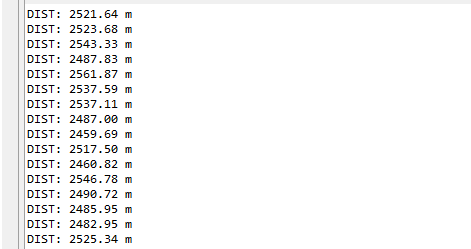
I am getting correct distance reading when using example codes.
Best Regards: Danish Riaz