I’m PhD student at MPEI and currently researching sources of error in UWB signals.
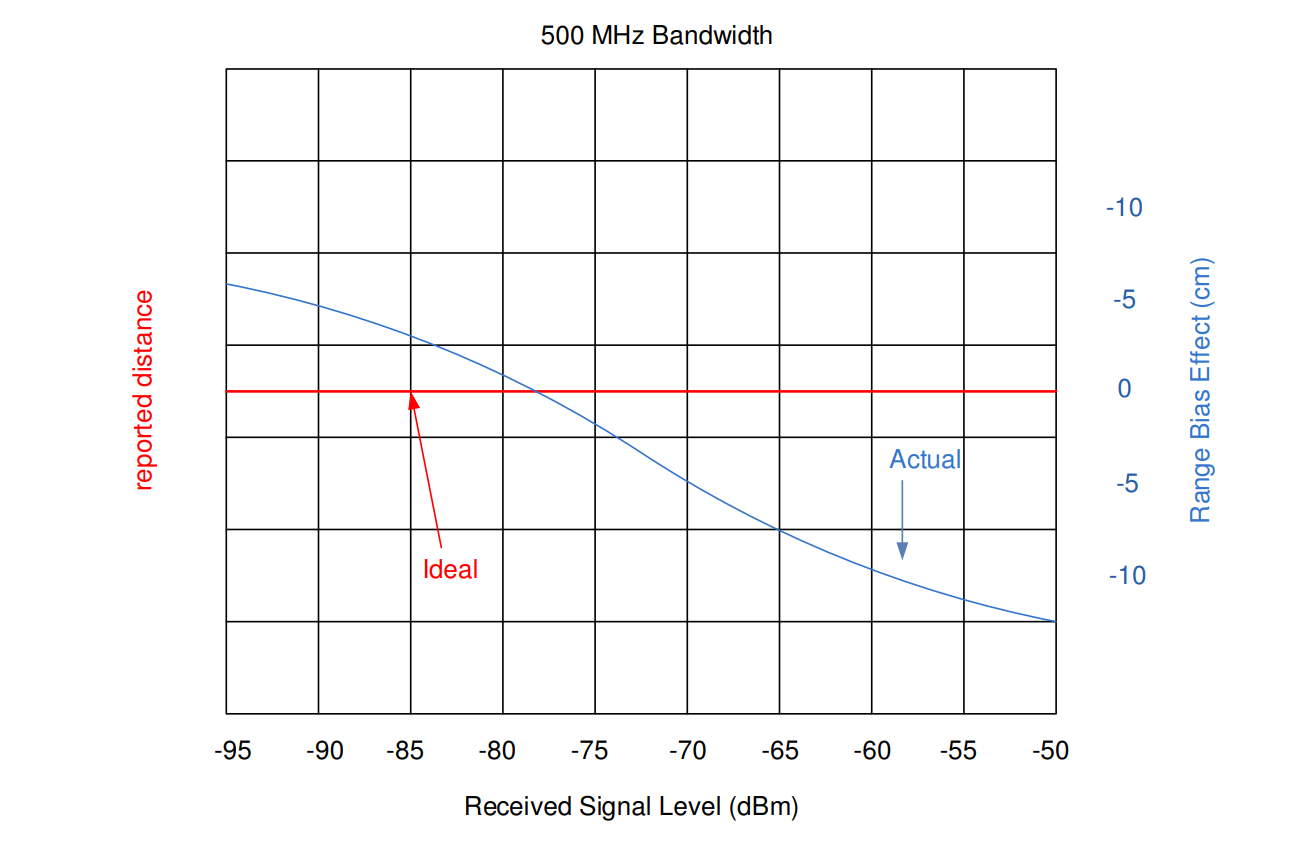
And recently I found interesting and mysterious note in Deca’s (Qorvo’s) documentation about non-linear Range-bias systematic error, dependent from received power level.
After some time spent for research I found no detailed information, where it comes from. So I tried to investigate it further and made a hypothesis, that this is cause of different threshold-crossing time.
I modeled this in MATLAB and my result doesn’t seem to be like a doc’s picture.
Can someone please provide more information about this source of systematic error?
Is direction of thought right or I’m totally mistaken?
Here is GitHub repo with detailed description of hypothesis and code.
I’ve approached this purely as an engineering issue to be solved rather than as a mathematical issue to model. This is probably repeating your thought process without adding anything useful but my mental model of the issue is:
The threshold is set based on background noise level and so will be a function of the environment but will be independent of the receive signal level.
All real world signals have a ramp up time, they don’t instantaneously jump from off to full strength.
A weaker signal will take the same time to reach their peak and follow the same ramp shape but with the amplitude reduced by a constant scale factor.
This means that all other things being equal a weaker signal will reach the threshold value later and so report a longer range.
The exact shape of the signal level to range error curve will be dependent on the nature of the signal, the physical characteristics of the output amplifier/antenna and the sensitivity characteristics of the receiving antenna and signal processing.
That’s about as deep as my analysis got. Since all of the things that control the shape of the curve are constant for my system I measured the shape of the curve and coded in a correction based on the results.
Another result of the above logic is that if different environments can have different noise levels then they will also have different detection thresholds. Which would in tern imply a different range bias for each environment. Technically we should get a different signal level to bias curve since the threshold is different but as a first approximation this will be a constant range bias related to the threshold level.
If we calibrate a system to give correct ranges in an open air environment and then put it in an electronically noisy office environment we see a bias in the range results. In theory by looking at the threshold level we could correct for this bias.
I do not think you can deduce this curve without knowing how the TOA detection of the pulse inside the DW1000 chip is implemented.
I’m personally not yet familiar with different pulse detection techniques, but did you survey the litterature of the publiclicly known techniques and models, and if they come with such a systematic bias or if you think that this surprisingly is only specific to the DW1000 ?
Just from the below two references, I see that the threshold selection and the pulse detection is a research field in itself.
Maybe, retrieving the cir data, trying to implement your own and compare to the first path index, could validate your assumptions.