I have a few questions regarding the operation of the DW1000 transceiver.
I am currently using the following configuration:
static dwt_config_t config = {
    5,                /* [chn] Channel number. */
    DWT_PRF_64M,      /* [prf] Pulse repetition frequency. */
    DWT_PLEN_128,     /* [txPreambLength] Preamble length. Used in TX only. */
    DWT_PAC8,         /* [rxPAC] Preamble acquisition chunk size. Used in RX only. */
    10,               /* [txCode] TX preamble code. Used in TX only. */
    10,               /* [rxCode] RX preamble code. Used in RX only. */
    0,                /* [nsSFD] 0 = use standard SFD, 1 = use non-standard SFD. */
    DWT_BR_6M8,       /* [dataRate] Data rate. */
    DWT_PHRMODE_STD,  /* [phrMode] PHY header mode. */
    (128 + 1 + 8 - 8) /* [sfdTO] SFD timeout. Used in RX only. */
};
As I understand it, during the transmission and reception process, the DW1000 performs cross-correlation between the transmitted and received preambles and stores 1,016 samples in the accumulator memory. Is this correct?
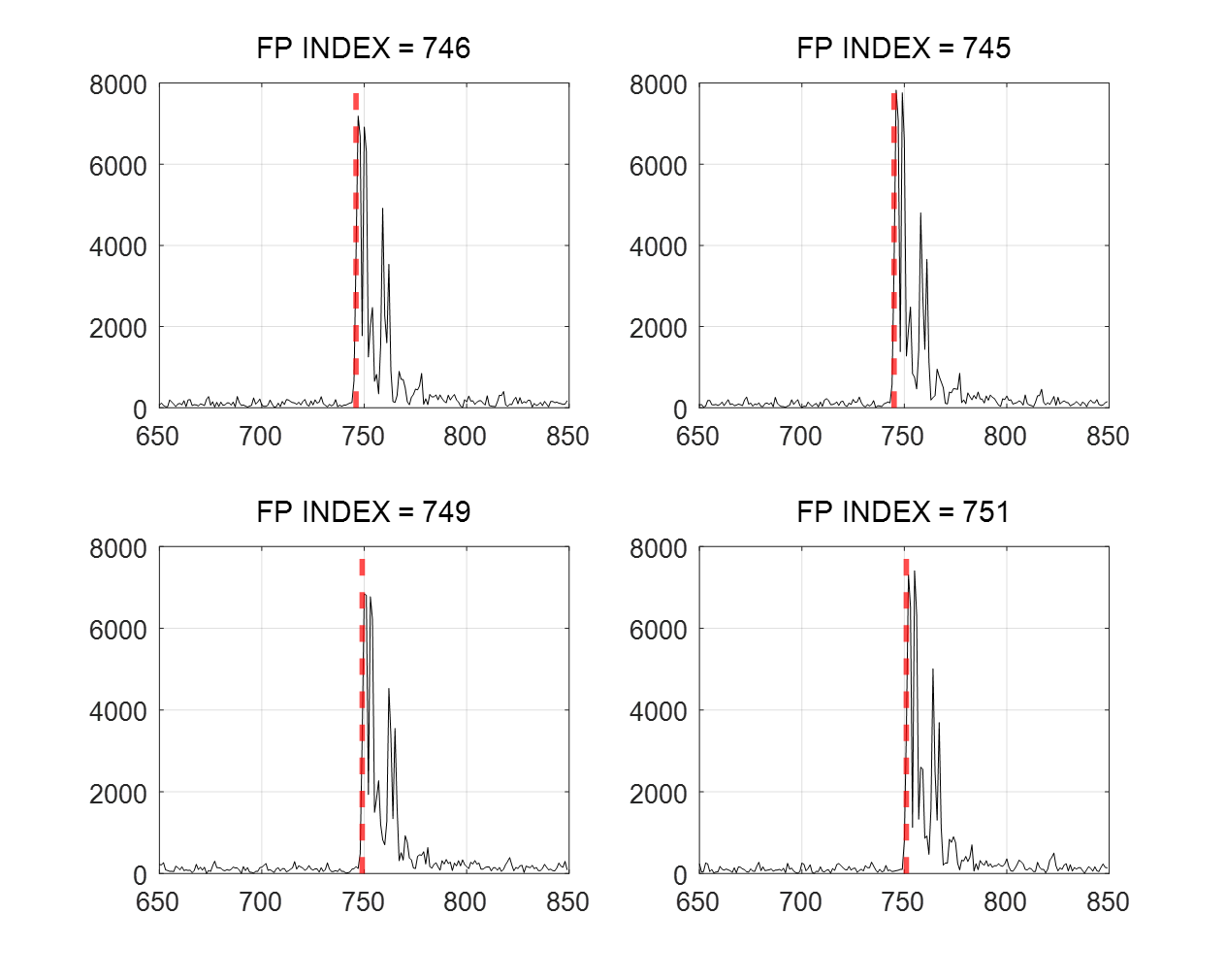
From several community discussions and my own data, I observed that the FP_INDEX (first path index) typically appears around 740–750, although it can shift slightly depending on the environment. However, even in a clear LOS condition, I noticed that FP_INDEX is not always fixed exactly at 750 but fluctuates slightly around it. Could you please explain why this variation occurs and how the reference position (around 750) is determined in the first place?
When a CIR index (for example, 750) is reported, what does that index specifically represent? Based on my understanding so far, the index itself does not carry an absolute time meaning, but rather serves as a reference for measuring delay differences between subsequent peaks (to analyze multipath components). In that sense, is it possible to calculate the Time of Flight (TOF) by combining FP_INDEX, RX_STAMP, and RX_RAWST values?
I am still new to this field, so please excuse any misunderstanding in my questions.
I would greatly appreciate your explanation.
I’ve never seen a definitive answer to this from Quorvo or decawave so the following is purly my speculation as to what is going on.
The receiver is looking for some indication that a signal reception has started. As soon as it sees this is starts the accumulation process.
When this decision to start is made it needs to align the accumulator windows with the incomming signal. However the exact timing of the signal is not known yet, all it can do is make a crude initial estimate which could be wrong. In order to allow the largest margin of error in this initial guess the obvious choice would be to place the initial estimate in the middle of the accumulator window. However since reflections can often be stronger than the direct signal there is a far higher probability that this inital guess is too late rather than being too early. Which means it’s better to place your inital guess around 3/4 of the way into your accumulator region.
The end result is that for most signals the FP_INDEX ends up between 740 and 750. Since the exact number depends on the accuracy of that initial guess (and possibly some internal clock divider resolutions) it’s not going to be fixed, if the inital guess was always correct you wouldn’t need the accumulator to calculate the timing.
Since the alignment between the accumulator and the internal clock is arbitary the FP_INDEX is completely useless when it comes to calculating ToF. Use the RX_STAMP value.
RX_RAWST is in effect FP_INDEX after allowing for CIR alignment. RX_STAMP then applies corrections based on a leading edge detection analysis of the CIR data and allowing for things like antenna delay.
The only time I’ve found RX_RAWST usefull is that occasionaly the correction system fails and you get what looks like a valid reception but the corrected RX_STAMP vaule is junk. This results in obviously incorrect ranges and so is easy to detect and filter out but performing a comparison between the raw and final rx times is a simple way to detect this problem early.
I always learn a lot from the answers you share across various communities.
However, I still haven’t fully understood, and here is my current understanding:
The RMARKER is recorded when the SFD is detected, so the receiver does not know exactly when the signal arrived while it is reading the preamble.
In the Qorvo algorithm, the initially estimated start point is taken as the timestamp at index 750 (out of 0–1016 accumulator samples) when calculating the CIR.
The parts I am still unclear about are:
How does this “initial estimate” manifest, and is there a way to verify it?
If the initial estimate is at index 300 and it is placed at index 750, the indices are shifted by 450 samples. In this case, what fills the CIR data in the preceding portion?
I would greatly appreciate it if you could clarify any misunderstandings I may have and answer my remaining questions.
Actually, it would be ideal to get a definitive answer from Qorvo, but I would also like to hear the opinions of experts.
The initial estimate doesn’t occur at any index, there is no index or accumulated data at that point.
There will be some form of shift register or cyclic buffer that is used to store data, this will be storing the preamble accumlation data. Once this crosses a threshold a frame is considered to be detected and the system will make as estimation of where the SFD will be expected to start. That will be used to give the alignment between the CIR data and the received signal.
But this is all speculation based on how I understand the device to be working and what seems like a logical way to impliment that functionality. What is actually going on will 1) only be known in detail to the people who designed the chip and 2) will be considered confidential IP and not something they are going to share even if you could find someone who knows to talk to. You may get someone to give you a high level description of the way it works in more detail than the user manual but I wouldn’t hold my breath if I was you.
Thank you, as always, for your quick responses. I appreciate and understand the points you mentioned.
It’s a bit unfortunate that we haven’t been able to receive a direct answer from the Qorvo UWB technical team.
It would be really helpful if there were clear examples available not only for the questions I asked but also for code demonstrating interactions with two or more anchors exchanging distance information.
It seems that such information is difficult to find .
(Of course, I’m not asking for the PANS code to be shared.)
Hopefully, in the near future, there will be more reference material available that we can use.