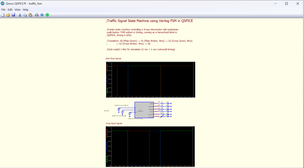
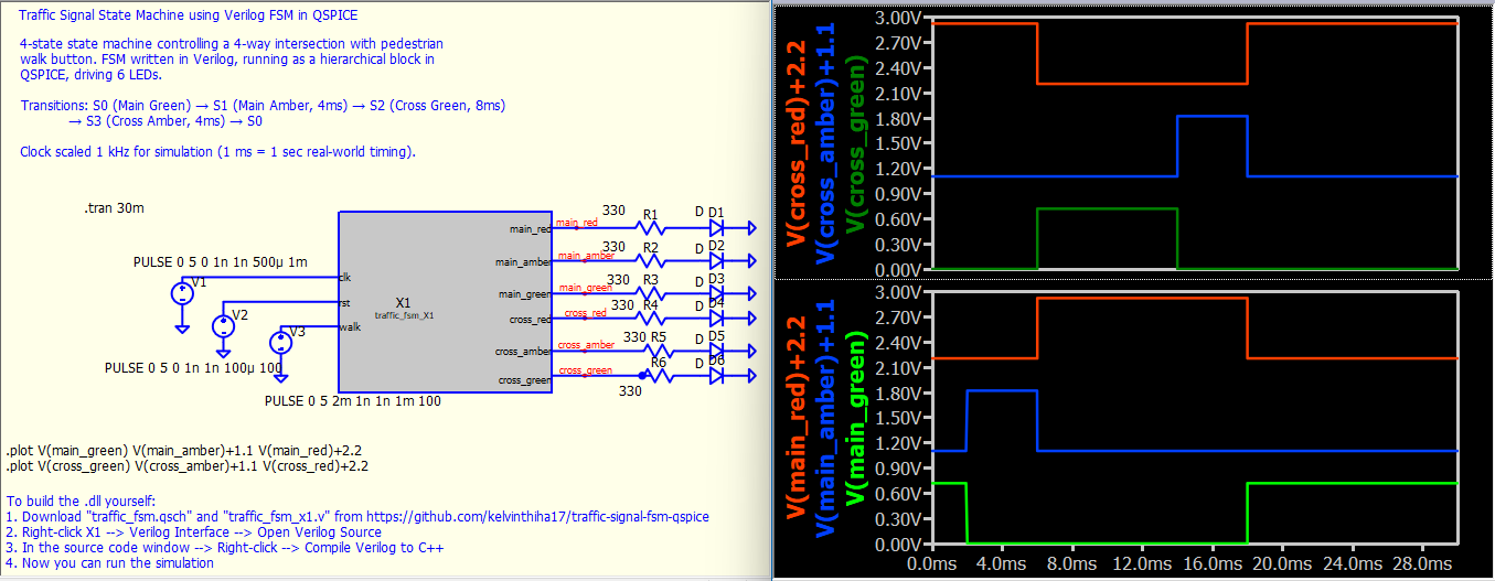
For this week’s QSPICE schematic capture, we have “Traffic FSM” by our friend Kelvin Ha, a Computer Engineering student at Rutgers University, graduating May 2027. Kelvin recently learned QSPICE and rebuilt his traffic signal FSM from scratch, this time as a Verilog module driving the LED output stages. State transitions verified in simulation. The project is here: GitHub - kelvinthiha17/traffic-signal-fsm-qspice: 4-state traffic signal FSM in Verilog, simulated in QSPICE with LED output stages · GitHub.
Please send any submissions to me at tim.mccune@qorvo.com (Schematic Capture Post #096)
2 Likes
Sharing a few tricks:
- A comment text box can be created by right-clicking a text box and selecting
This text is a comment, or by hovering over a text box and using the shortcut ; to toggle it. There is no need to put a “;” in front of a text line, unless a text box mixes directives and comments where you need the entire text box to be active.
- To plot a logic sequence, my practice is to add an offset to each logic signal in the .plot directive so it looks more like a logic analyzer output. By the way, the
.plot command sets up the plot after the simulation is executed, reducing the need to capture the output window and paste the bitmap back onto the schematic, which makes the .qsch file very large! (In this case, traffic_fsm.qsch is 18MB on GitHub, by removing both bitmap, .qsch is only 12.2KB)
- Include instructions on how to run the example with the Verilog source, in case anyone wants to run this example without blindly using the .dll file and prefers to compile it from the provided Verilog source code instead.
traffic_fsm.qsch (12.2 KB)
2 Likes