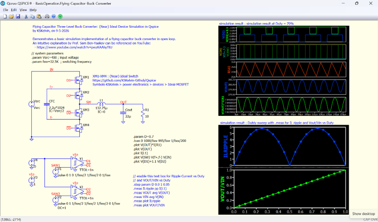
For this week’s QSPICE Schematic Capture, we have a flying-capacitor three-level buck converter by our friend Kelvin Leung.
Kelvin’s open-loop simulation uses four ideal MOSFETs and a flying capacitor to generate a three-level switching waveform from a 400 V input. At the illustrated 70% duty cycle, the converter produces approximately 280 V—exactly what the ideal buck-converter relationship predicts.
The QSPICE schematic also performs a duty-cycle sweep and automatically measures both the output-voltage conversion ratio and inductor-current ripple. The results clearly show the linear relationship between VOUT/VIN and duty cycle, as well as the distinctive variation in ripple produced by the three-level topology.
This is a great example of how QSPICE can place the circuit, switching waveforms and swept measurements together in one self-documenting simulation.
Kelvin has also provided an explanatory video:
Thanks to Kelvin for creating and sharing another excellent QSPICE example.
I plan to do that, but it depends on when I have time to get to it.
I have a lot of circuit examples, but preparing them for the public domain takes time.
This would be AWESOME! Especially for us newbies where we can quickly download and test a topology to familiarize ourselves with.
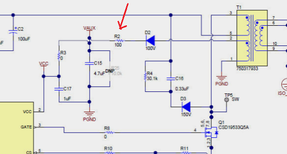
The reason for my current interest is that I am currently reviewing TI’s LM5155x controller as well as reading over the “How to Design an Isolated Flyback Using the LM5155” SNVA866A design guide. What struck me as a bit odd is having a series resistor in the path of the auxiliary voltage winding as that would dissipate power. I wanted to see if there was an isolated flyback converter also using an auxiliary power and if implemented a bit differently or if they instead opted for a primary side small voltage regulator to supply Vcc to the controller.
Any insight as to why a resistor would be placed in series? This seems counter intuitive. But then again, I am a bit new to this so maybe I am overlooking something.