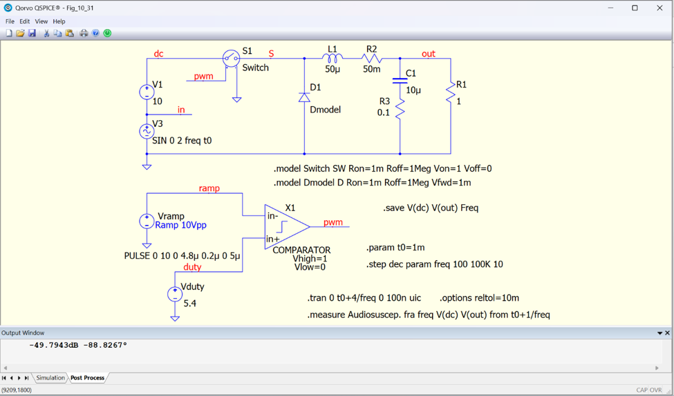
For this week’s QSPICE schematic capture, we have one from our friend Professor Marcos Alonso and his recent book, available here. This QSPICE schematic models the averaged small-signal response of a PWM buck converter for audio susceptibility analysis. By using an averaged switch model and sweeping input disturbance frequency, the circuit reveals how ripple and noise on the input affect output regulation across frequency.
Why simulate it in QSPICE? QSPICE makes it practical to analyze complex switching power systems with exceptional speed and convergence. Using averaged models, engineers can study loop behavior, input susceptibility, and stability in seconds rather than minutes—accelerating optimization long before hardware is built.
(Schematic Capture Post #093) Please send any submissions to tim.mccune@qorvo.com.