I had the same question this morning, and I just performed a quick check. It appears that a number of recent updates are related to the MOSFET model, particularly bug fixes or improvements to the BSIM3 model, as indicated in the revision history.
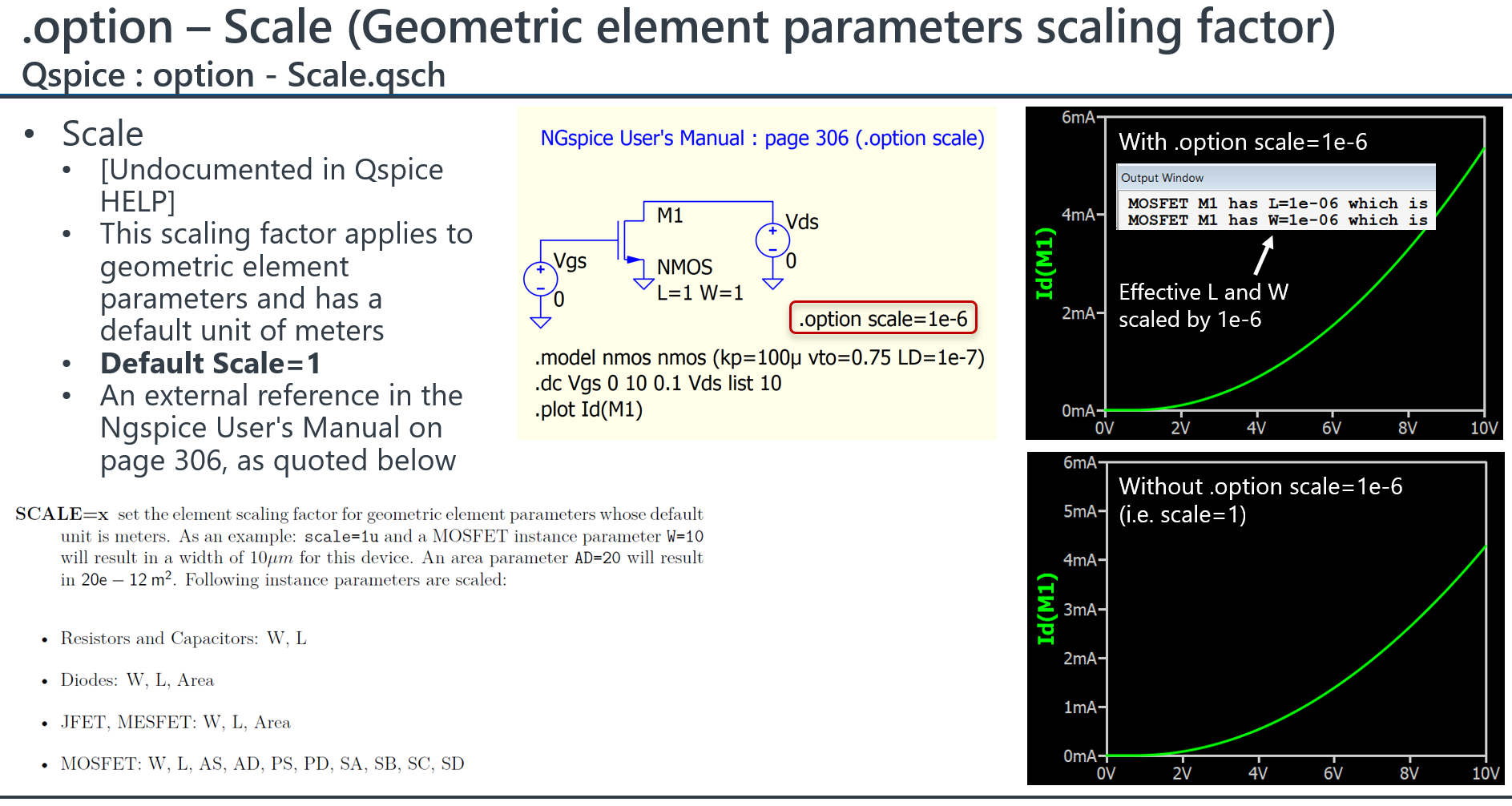
This option can be found in NGspice and Hspice. Referring to the NGspice user’s manual and conducting a quick verification test, it appears to be a scaling factor for geometric element parameters. It is likely relevant to microelectronic and IC design areas.
I was trying to use the sky130 open source pdk (devloped for ngspice, compatible with hspice) in Qspice, since it doesn’t have any gui and it’s commands are somewhat time consuming for me to write. Powerful but not as easy you find in ltspice or Qspice.
I asked Mr. Engelhardt to support this pdk. He did many changes for Qspice to navigate the pdk’s folder structure properly, added the gauss(,) and agauss(,) functions and also implemented this scale factor. Very grateful to him.
Are you referring to this? Do you mean that the open-source PDK includes spice models for devices in this 130nm node? I’m not involved in microelectronics, but it sounds very interesting, and thank you for sharing.
The Google version is old now, not maintained anymore. The efabless fork is updated and maintained regularly.
This is the foundry provided primitives library for example.
Hello KSKelvin,
your plot shows, that there is a slight difference with and without scale factor. But I think, the difference will be better visible if you do a transient simulation with some resistor in the gate line. In your setup the current is defined by some properties and scaled with W/L, so the scale factor doesn’t show a big effect.
But if you do it transient the gate input capacitance is defined by a W*L, so the difference will be much better visible.
My intention was simply to explain what the “.option scale” does. The reason I chose Id vs Vgs as a demonstration is because I know it can be affected by W (width) and L (length), with lateral diffusion (LD) included. I agree that there may be other parameters that could provide a better demonstration. However, since I’m not an expert in FET modeling, I don’t have extensive knowledge regarding which parameters are most sensitive to W and L.