I’d like to share a new repository created to provide the QSpice community with example circuits. Currently, there are over 170 QSpice schematics uploaded, serving as a supplementary resource for the Symbols-KSKelvin library.
 QSpice-Circuits / Qspice-examples
A quick note on symbols:
All circuit examples are completely standalone because subcircuits are embedded directly into the symbols — so you can run them right away. However, if you’d like to use the custom symbols from the Symbols-KSKelvin library yourself, you can download the library from my primary repository:
KSKelvin QSpice Symbol Library
Hope you find these examples helpful! Feel free to check them out or share any feedback.
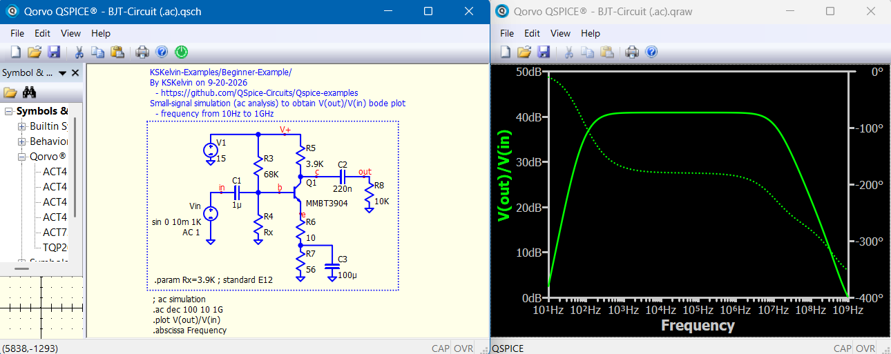
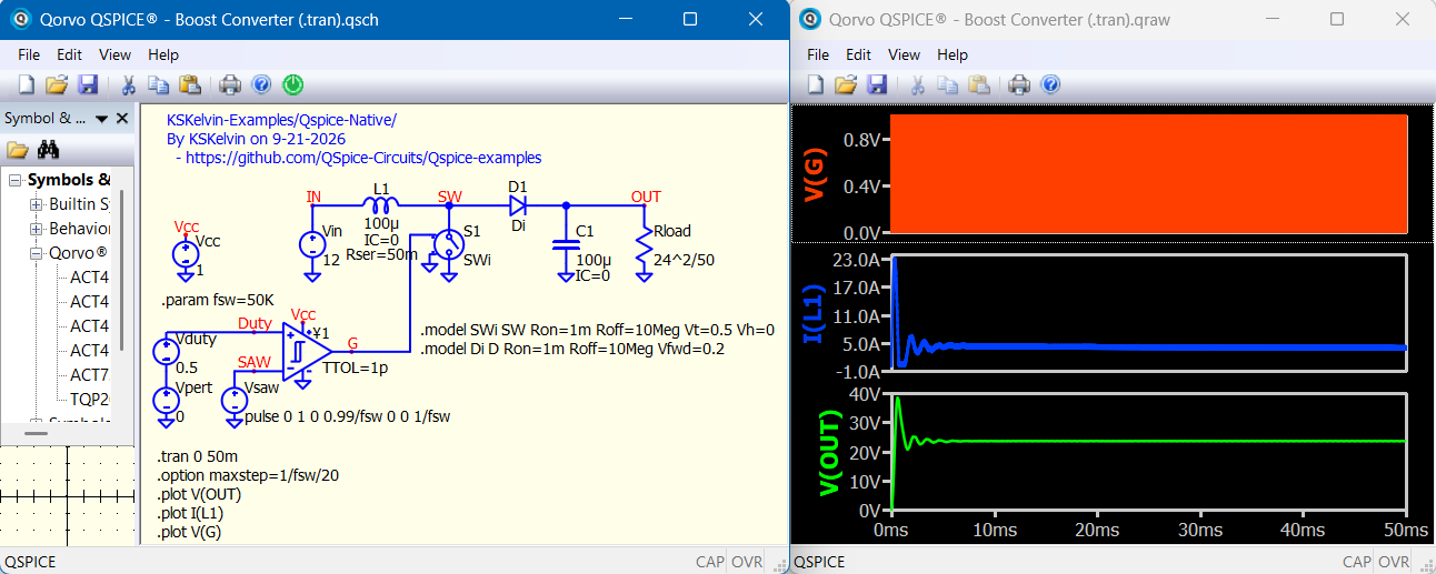
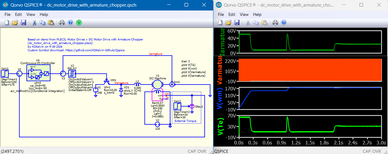
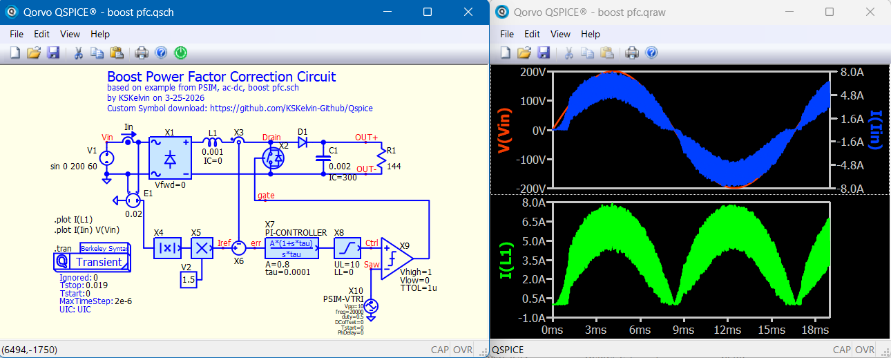
Here are a few screenshots of how the examples look.
\KSKelvin-Examples\Beginner-Examples\BJT-Circuit (.ac).qsch
\KSKelvin-Examples\Qspice-Native\power-electronics\dc-dc\Boost Converter (.tran).qsch
\PLECS-DemoModels\Motor Drives\dc_motor_drive_with_armature_chopper.qsch
\PSIM-Examples\ac-dc\boost pfc.qsch
6 Likes
I am reviewing your flyback converter circuit with three outputs (+15V/-15V, +5V). Only the +5V output has a compensator associated with it - the other two do not. Is this how a real world design would be implemented or was only one implemented for brevity (voltage mode control)?
Would implementing a flyback converter with currend mode control be more practical?
I assume you are referring to this example. Those demo models were ported to QSpice as closely to their original setups as possible:
\PLECS-DemoModels\Power Supplies\flyback_converter_with_analog_controls.qsch
Yes, in multi-output designs, feedback is typically taken from a single output. For example, on page 12 of this TI application note, the +5V/3A output is regulated directly, while the remaining two outputs rely on linear regulators if tight accuracy is required.
TI - Isolated Multiple Output Flyback Converter Design Using TL494
That PLECS example operates in DCM (Discontinuous Conduction Mode), where voltage-mode control works well because there is no right-half-plane (RHP) zero in the power stage’s transfer function. In practical designs, however, you would still want to sense switch current for overcurrent protection in voltage mode. For a flyback operating in CCM (Continuous Conduction Mode), current-mode control is generally preferred to avoid dealing with RHP zero dynamics.
1 Like
How do you determine which one? Is there a general rule of thumb?
I have seen arguments made for both primary and secondary. In your opinion, where should the current sense be implemented?
In my experience, closed-loop feedback usually comes from the highest-power output. For current sensing, flyback commonly measures primary-side current with a sense resistor or reply on Rds,on.
Thank you for responding.
Yes, this aligns with the research that I have been doing.
Much appreciated!