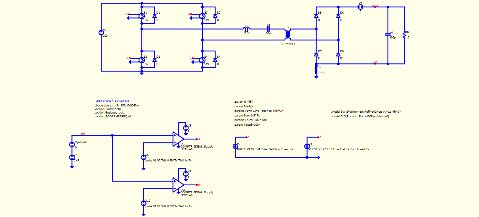
What I am doing wrong? As the bode plot result obtained in qspice needs to be somehow close or the same with the bode plot result given in the above article…
There are multiple subjects that you need to consider from this paper.
On page 3, it is mentioned that the switching frequency is slightly greater than the resonance frequency, which is set to fs=55kHz. However, the bode plot in paper extends up to 10e7 rad/sec (which is 16MHz), far beyond the switching frequency. The Bode plot in the paper may only be accurate in its mathematical small signal model but not in practical implementation. Normally, the .bode method in simulations only goes up to frequencies lower than the switching frequency.
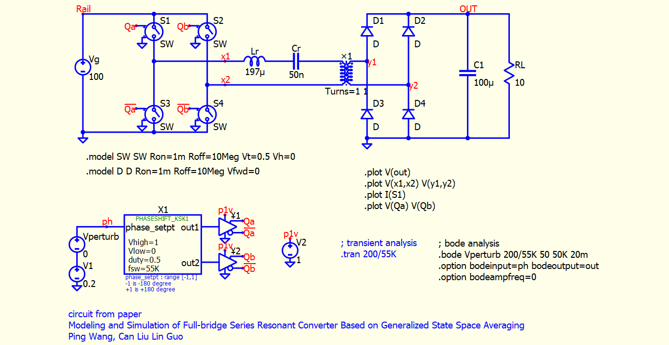
In figure 3.6, the closed-loop schematic suggests that the gate signal is from phase shift. The high and low side switches are complementary, with a phase shift between the two half bridge pairs. Therefore, I believe that the duty cycle (D) mentioned in this paper is actually the phase-shift ratio.
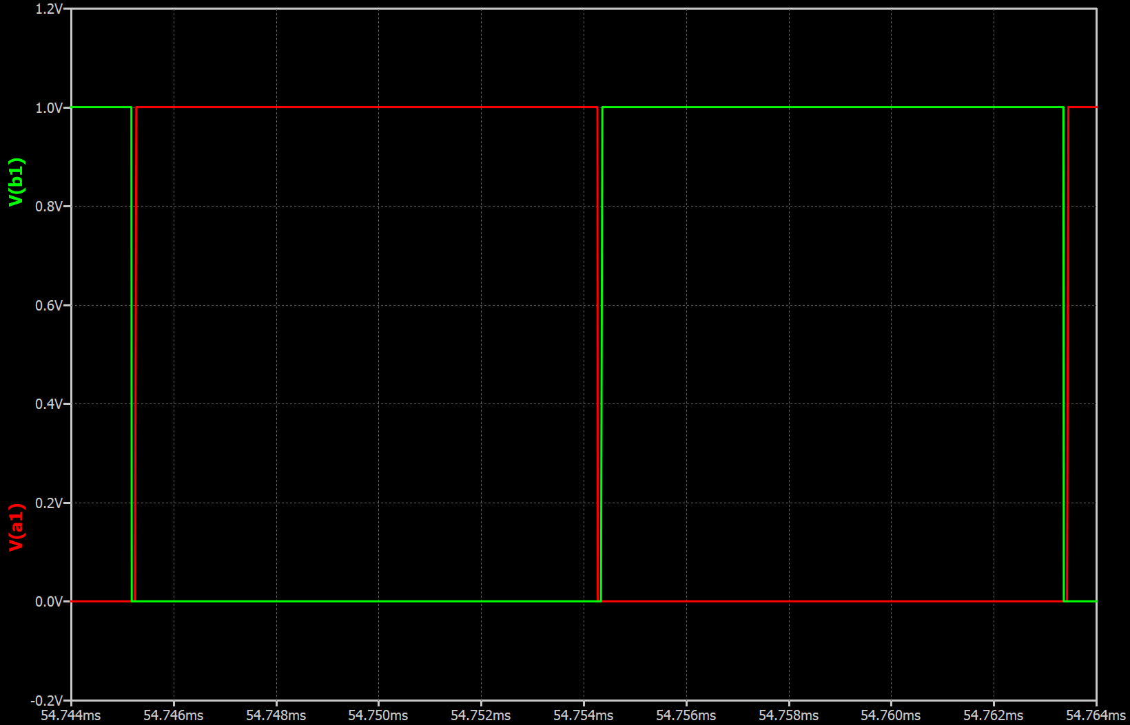
Since I am not familiar with your gating circuit, for the phase-shift full bridge, I used the phase shift symbol from my symbol library and created this circuit to simulate the open-loop circuit as shown below. I assume that in figure D=0.2, the represented phase can give a duty cycle of 0.2. (I set my voltage source phase to 36 degrees)
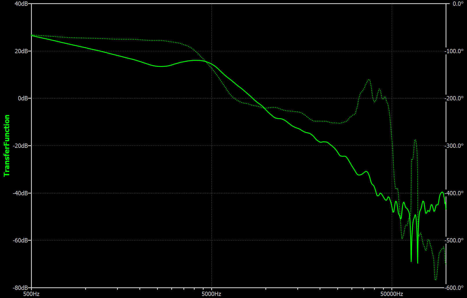
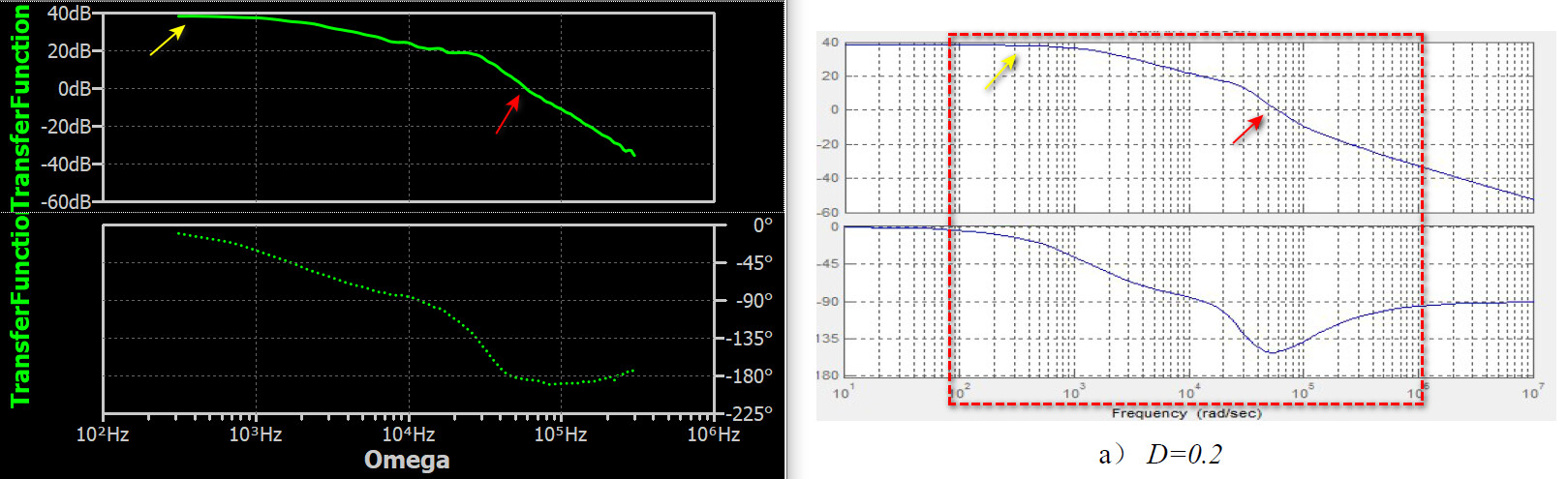
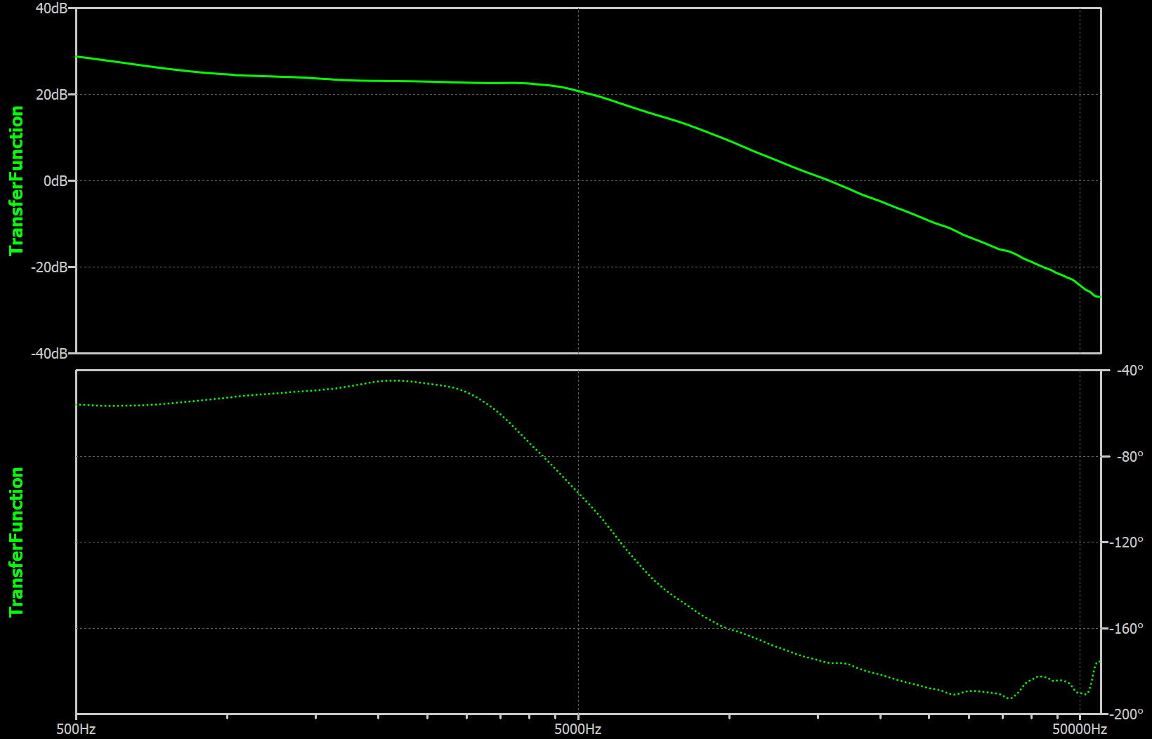
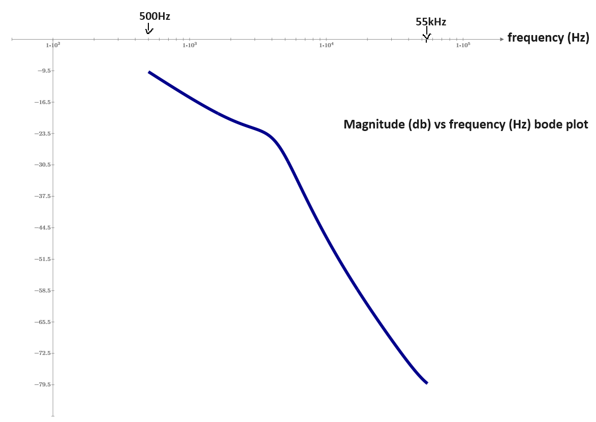
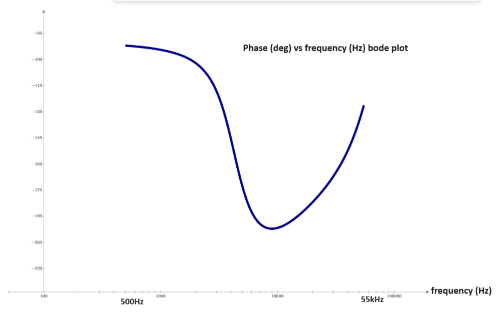
Here is a comparison with x-axis changed to Omega (2pif) and compare to Fig 3.2 (a) where D=0.2. Gain profile looks close, and phase profile drop quicker after than the paper after 1e4 rad/sec. But generally speaking, simulation and this paper still match.
It is always a challenge to replicate the results of others, as sometimes they may not include every detail of how they set up the simulation. I only guess what their setup is. I didn’t verify other duty, as I am not sure if the switching frequency have to adjust to have ZVS for other duty to get the bode. But the purpose only to demonstrate to you, your modeling determine what you get and replicating this type of circuit you have to understand all detail including how to setup a proper gating circuit.
So, the only idea is to learn how to take the correct bode plot for dc dc resonant converters. I put firstly this example from this article in order to have some heavily reference comparison.